Power factor correction controller

a technology of power factor and controller, applied in the direction of electric variable regulation, process and machine control, instruments, etc., can solve the problems of low conversion efficiency and complex control, and achieve the effect of enhancing the overall conversion efficiency and conversion power, and low conversion efficiency

Inactive Publication Date: 2007-10-25
WU TSAI FU
View PDF5 Cites 25 Cited by
  • Summary
  • Abstract
  • Description
  • Claims
  • Application Information

AI Technical Summary

Benefits of technology

[0009] In view of the foregoing shortcomings, the present invention provides a power factor correction controller that can simultaneously control several power converters to be operated at a critical conduction mode, so as to enhance the overall conversion efficiency and conversion power of the power factor corrector and overcome the shortcomings of the traditional power factor corrector operated in a critical conduction mode having a limitation on the conversion power and a drawback of a low conversion efficiency.

Problems solved by technology

In general, an electric company prefers simply connecting a resistor load to a power circuit to producing currents with a high-peak value, since the currents with a high-peak value may fuse a circuit breaker easily and cause a disorder to a voltage regulating circuit.
Since the power switch of the power converters is operated at a compulsory switching mode, therefore the UC3854 IC has the disadvantage of a low conversion efficiency.
For a high conversion power, it requires other auxiliary circuits to flexibly switch the power switch of the main circuit in order to improve the conversion efficiency, and thus additional control of at least one set of auxiliary circuits is needed, and the control will become very complicated.
However, the input current ripple of the power factor corrector operated at the critical conduction mode is larger, and thus requiring a specification for larger components and a pre-filter to achieve the power factor correction, since its conversion power is usually not high (or below 100W).

Method used


Image

  • Power factor correction controller
  • Power factor correction controller
  • Power factor correction controller

Examples


Embodiment Construction

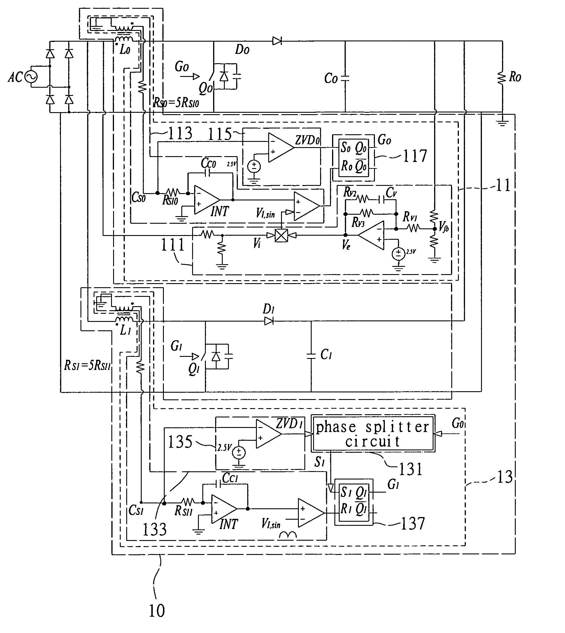
[0025] The present invention relates to a critical conduction mode power factor correction controller of an alternating frequency conversion control. The power factor correction controller is coupled to a power input terminal of a power stage circuit for controlling the high power factor and low harmonics of the power stage circuit and mainly obtaining a voltage signal and a current signal of the public utility electricity inputted from the power stage circuit (or obtaining the related signals between the voltage signal and current signal) together with the output voltage signal to determine a correct gate control signal of the power switch component, and then use the high frequency switching characteristic of the power switch to force the input current to follow the reference current signal, so as to control the input current and input voltage of the power stage circuit to have the same phase and maintain the function of a sine-wave waveform. The present invention adopts a pluralit...


PUM


Abstract

A power factor correction controller simultaneously controls several power converters to be operated at a critical conduction mode to improve the overall conversion efficiency and conversion power of the power factor corrector. The controller includes a primary power converter control circuit for feeding back an input voltage signal, an output voltage signal and a primary current signal, and outputting a primary gate control signal for controlling a primary power switch; at least one secondary power converter control circuit for receiving the primary gate control signal and outputting a secondary gate control signal for controlling a secondary power switch; and a phase splitter circuit for receiving the primary gate control signal to control a gate output driving circuit, so that the gate output driving circuit outputs the secondary gate control signal.

Description

BACKGROUND OF THE INVENTION [0001] 1. Field of the Invention [0002] The present invention relates to a power factor correction controller, and more particularly to a power factor correction controller capable of simultaneously controlling several power converters to improve the overall conversion efficiency and conversion power of a power factor corrector. [0003] 2. Description of Related Art [0004] Since the present household or industrial electric appliances have a voltage difference with the input power supply terminal (such as a public utility electricity terminal) or even have an input current with a high-peak factor (harmonics), and thus the quality of electricity drops, and it is necessary to have a power factor corrector for the power factor correction and harmonic suppression. The main function of the power factor corrector is to compensate the phase difference of the current with respect to the voltage of the electric appliances and suppress the harmonic current produced b...

Claims


Application Information

Patent Timeline
Patent Type & Authority Applications(United States)
IPC IPC(8): G05F1/00
CPCG05F1/70Y02B70/126H02M3/1584H02M1/4225Y02B70/10
Inventor WU, TSAI-FUCHEN, YAOW-MINGTSAI, JIUN-REN
Owner WU TSAI FU
Why Eureka
Try Eureka