Display control device, image processing apparatus and display control method

a display control and image processing technology, applied in the field of interface screens, can solve problems such as inevitably reducing user's work efficiency

Active Publication Date: 2007-10-25
KK TOSHIBA +1
View PDF8 Cites 47 Cited by
  • Summary
  • Abstract
  • Description
  • Claims
  • Application Information

AI Technical Summary

Benefits of technology

[0007]An embodiment of the present invention has been made in order to solve the problems described above. An object of this invention is to provide a technique of displaying display objects, such as icons, which correspond to a process object to be subjected to a specific process, at appropriate positions on a screen, thus providing convenience on the part of the user.

Problems solved by technology

The conventional interface screen is disadvantageous, because the set items cannot be seen at a glance and the user's work efficiency is inevitably reduced.

Method used


Image

  • Display control device, image processing apparatus and display control method
  • Display control device, image processing apparatus and display control method
  • Display control device, image processing apparatus and display control method

Examples


Embodiment Construction

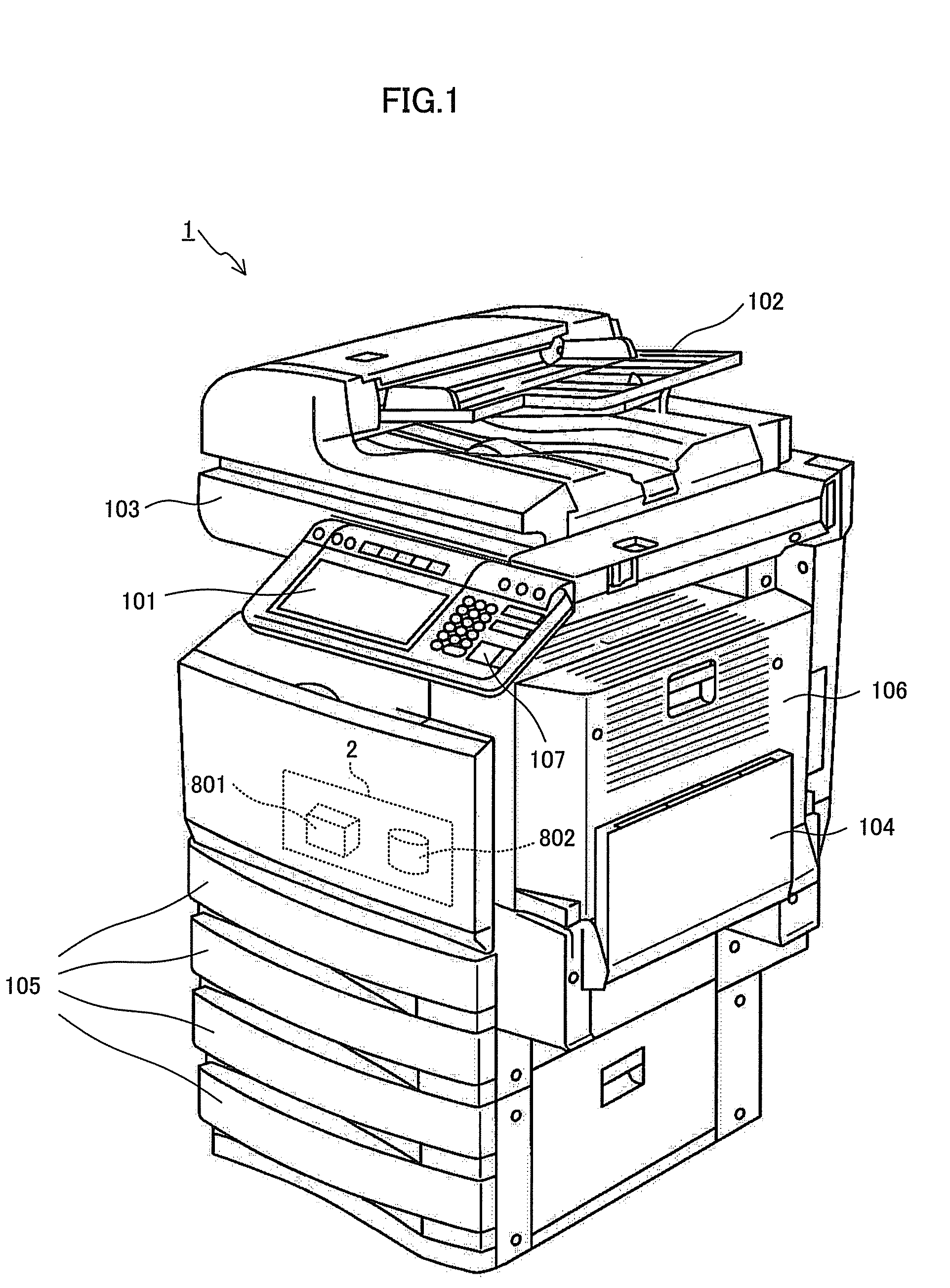
[0020]An embodiment of the present invention will be described, with reference to the accompanying drawings. FIG. 1 is a perspective view explaining the basic configuration of an image processing apparatus 1 having a display control device 2 according to an embodiment of this invention. The image processing apparatus 1 is, for example, a multi function peripheral (MFP).

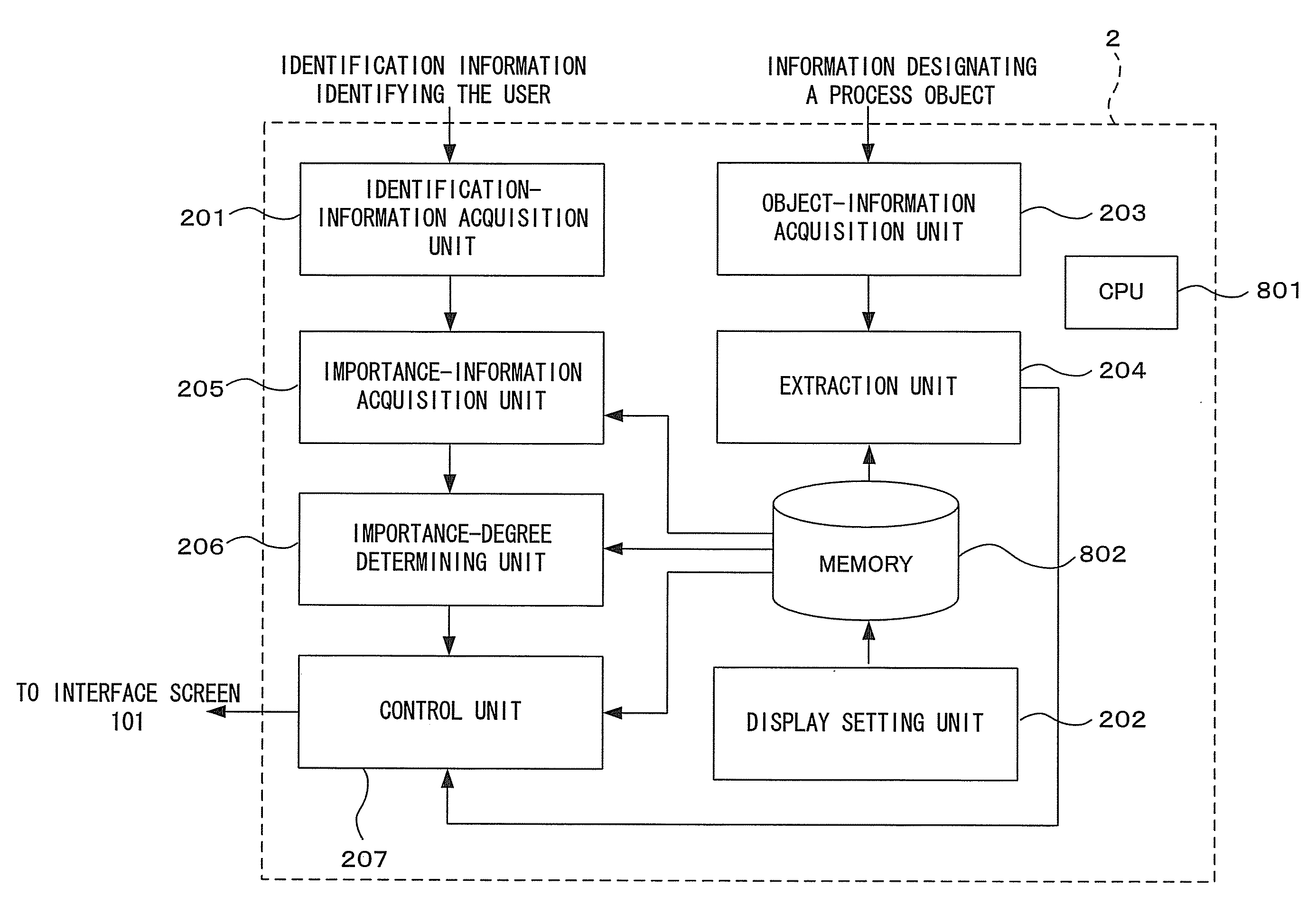
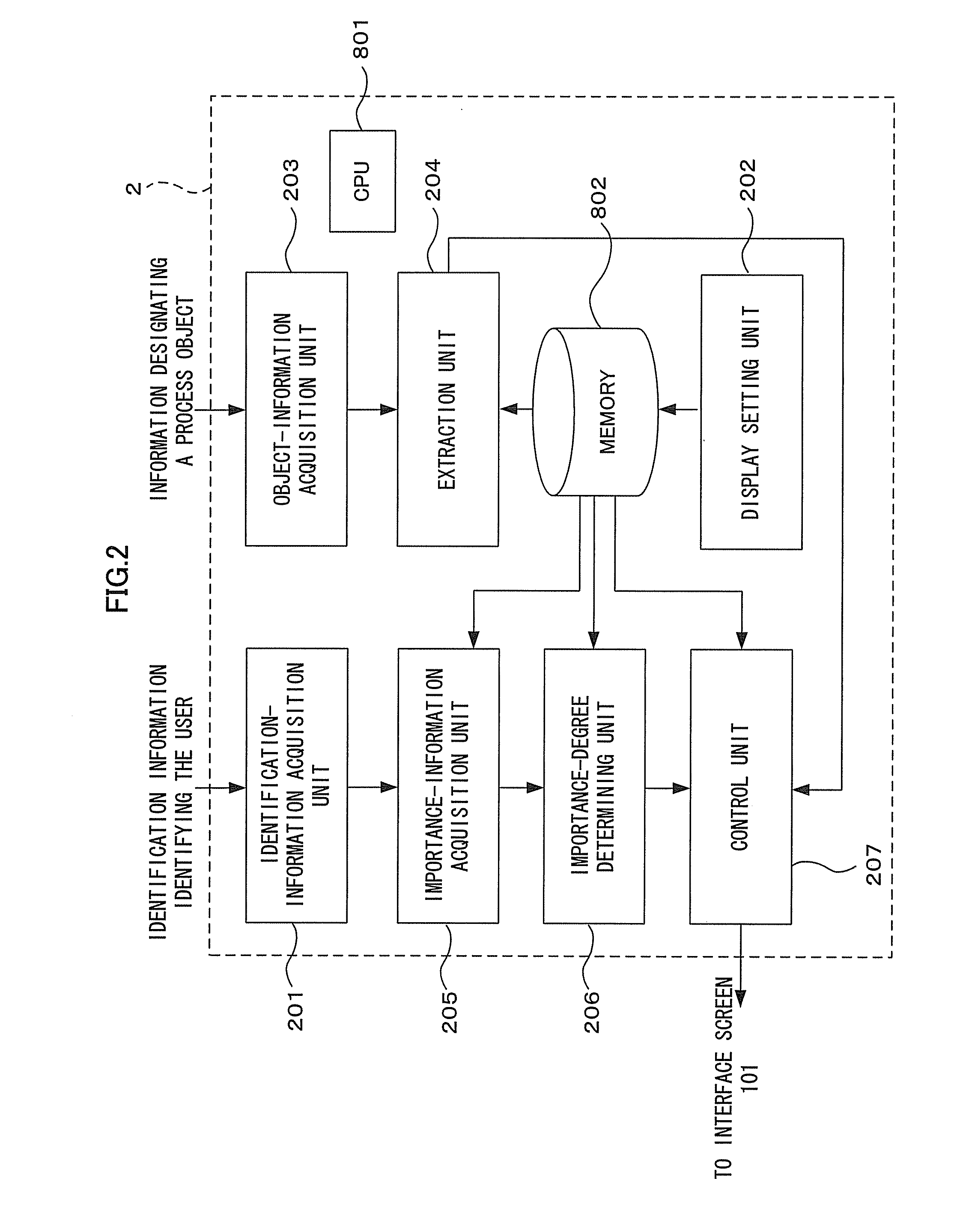
[0021]The image processing apparatus 1 according to the present embodiment comprises an interface screen 101, an auto document feeder (ADF) 102, an image-reading unit 103, a manual sheet-feeding unit 104, a sheet cassette 105, an image-forming unit 106, an authentication process unit 107, and a display control device 2.

[0022]How the image processing apparatus 1 operates will be briefly explained with reference to the accompanying drawings. Assume that the image processing apparatus 1 is set in copy mode to perform a copy process (i.e., a prescribed image processing). First, the authentication process unit 107 authenti...


PUM


Abstract

A technique is provided, which can display objects, such as icons corresponding to a process object which will be subjected to a specific process, at appropriate positions on a screen, thus providing convenience on the part of the user.
A display control device is provided, which can display, on a screen, a plurality of display objects related to a process object to undergo a predetermined process. The device comprises: an object-information acquisition unit that acquires information for identifying the process object; an extraction unit that extracts, from the display objects, some display objects having a specific relation with the process object identified on the basis of the information acquired by the object-information acquisition unit; an importance-information acquisition unit that acquires information representing a degree of importance that the display object extracted by the extraction unit has in connection with display on the screen; and a control unit that displays display the display objects extracted by the extraction unit in accordance with the information acquired by the importance-information acquisition unit in a display region composed of substantially ring-shaped first to n-th regions (n is 2 or a greater integer) concentric to one another, such that a display object having a higher degree of importance than a display object displayed in an x-th region is displayed in an (x−1)th region located inside the x-th region (x is 2 or a greater integer).

Description

BACKGROUND OF THE INVENTION[0001]1. Field of the Invention[0002]The present invention relates to an interface screen that displays display objects such as characters and icons. More particularly, the invention relates to a technique of controlling the displaying of display objects on interface screens.[0003]2. Description of the Related Art[0004]Hitherto, to set conditions of processing images, on an interface screen, the icons (display objects) corresponding to items desired are selected from the items classified under tabs or the like and are then set on the interface screen.[0005]On such a conventional interface screen, the items that can be set to perform a process are arranged over a plurality of tabs (setting menus). (See, for example, Jpn. Pat. Appln. Laid-Open Publication No. 11-194669 and Jpn. Pat. Appln. Laid-Open Publication No. 9-269702.)[0006]On the conventional interface screen, the user must find the icon corresponding to the desired item to set, while switching a plu...

Claims


Application Information

Patent Timeline
Patent Type & Authority Applications(United States)
IPC IPC(8): G06F3/12G06F3/0482G06F3/0481
CPCG06F3/04817G06F3/0482H04N1/00411H04N1/00413G03G15/502H04N1/00466H04N1/00482H04N2201/0094H04N1/00424
Inventor NAKAMURA, MAHINASATO, MAKIMOTEGI, TSUNEHIROOKUMA, YUMIKOSASAKI, YASUTSUGU
Owner KK TOSHIBA
Why Eureka
Try Eureka