Method of manufacturing electrode pattern

Inactive Publication Date: 2007-10-25
SAMSUNG ELECTRO MECHANICS CO LTD
View PDF8 Cites 5 Cited by
  • Summary
  • Abstract
  • Description
  • Claims
  • Application Information

AI Technical Summary

Benefits of technology

[0012] An advantage of the present invention is that it provides a method of manufacturing an electrode pattern, in which several-hundreds layers of electrode patterns required by a laminate-type electronic part can be patterned to have a thickness of less than 1 μm in a short time.
[0013] Additional aspect and advantages of the present general inventive concept will be set forth in part in the description which follows and, in part, will be obvious from the description, or may be learned by practice of the general inventive concept.
[0014] According to an aspect of the invention, a method of manufacturing an electrode pattern comprises preparing a first support film; forming a mold release pattern on one surface of the first support film, the mold release pattern defining an internal electrode formation region; forming an electrode layer on the mold release pattern by using a thin film technique; preparing a second support film; forming a transfer target layer on one surface of the second support film; disposing the electrode layer of the first support film and the transfer target layer of the second support film such tha

Problems solved by technology

However, since the metallic powder is manufactured of paste or slurry, there has been a tec

Method used


Image

  • Method of manufacturing electrode pattern
  • Method of manufacturing electrode pattern
  • Method of manufacturing electrode pattern

Examples


Example

First Embodiment

[0030] First, a method of manufacturing an electrode pattern according to a first embodiment of the invention will be described with reference to FIGS. 1A to 1E.

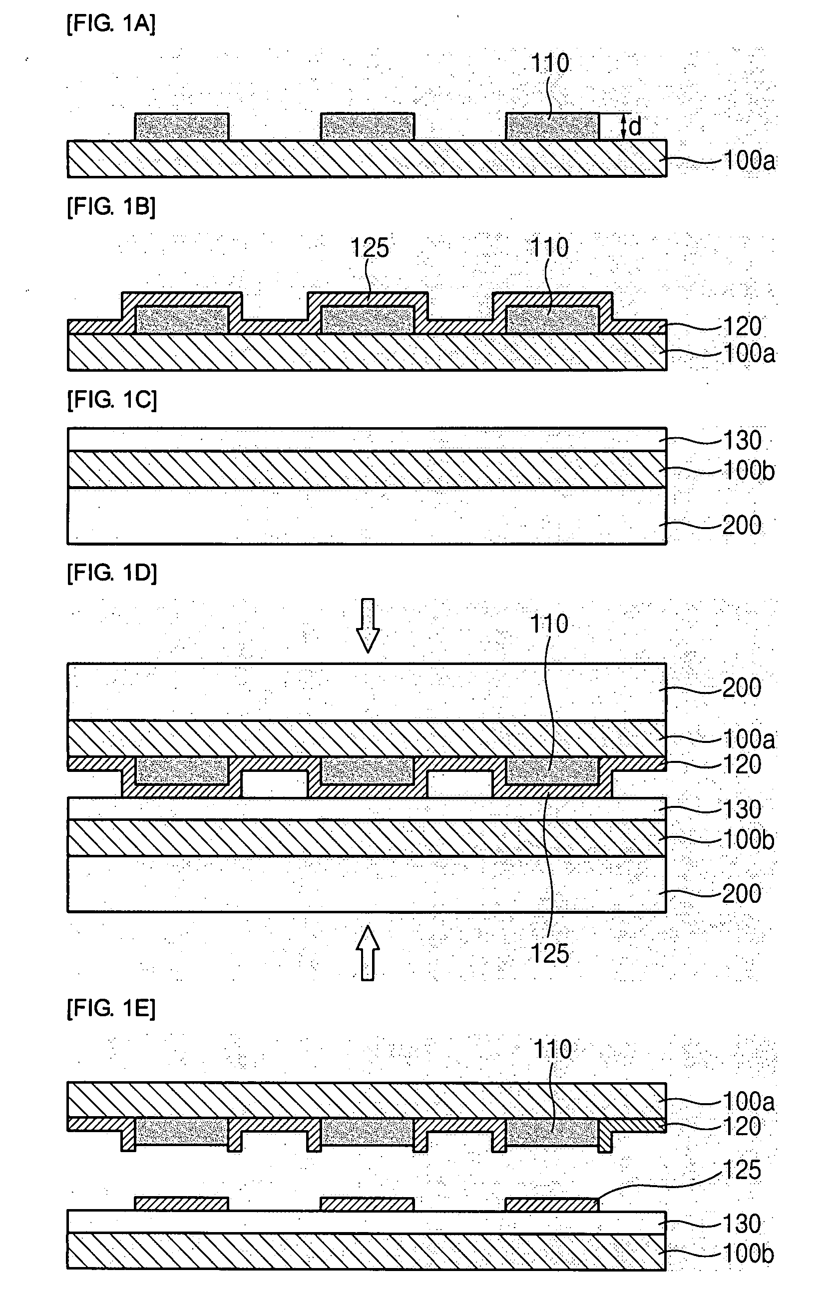
[0031]FIGS. 1A to 1E are sectional views sequentially showing a process for explaining the method of manufacturing an electrode pattern according to the first embodiment of the invention.

[0032] As shown in FIG. 1A, a first support film 100a composed of PET, PBT or the like is prepared.

[0033] Next, a mold release pattern 110 is formed on one surface of the first support film 100a, the mold release pattern 110 defining an internal electrode formation region.

[0034] More specifically, the mold release pattern 110 is formed as follows. First, mold release forming liquid is printed in a desired pattern, that is, in a shape of an internal electrode pattern on one surface of the first support film 100a by a printing method such as screen printing, gravure printing, ink-jet printing, laser printing or the like. N...

Example

Second Embodiment

[0055] Now, a method of manufacturing an electrode pattern according to a second embodiment of the invention will be described with reference to FIG. 5. However, the descriptions of the same components of the second embodiment as those of the first embodiment will be omitted.

[0056]FIG. 5 is a sectional view for explaining the method of manufacturing an electrode pattern according to the second embodiment of the invention.

[0057] The method of manufacturing an electrode pattern according to the second embodiment has almost the same construction as the method of manufacturing an electrode pattern according to the first embodiment. As shown in FIG. 5, however, the method of an electrode pattern according to the second embodiment further includes forming a mold release layer 115 on one surface of the first support film 100a, before the mold release pattern 110 defining an internal electrode formation region is formed on the one surface of the first support film 100a. ...


PUM


Abstract

A method of manufacturing an electrode pattern comprises preparing a first support film; forming a mold release pattern on one surface of the first support film, the mold release pattern defining an internal electrode formation region; forming an electrode layer on the mold release pattern by using a thin film technique; preparing a second support film; forming a transfer target layer on one surface of the second support film; disposing the electrode layer of the first support film and the transfer target layer of the second support film such that the electrode layer and the transfer target layer face each other; thermally compression-bonding the first and second films disposed to face each other such that the electrode layer positioned on the mold release pattern is transferred onto the transfer target layer; and separating the first and second films from each other.

Description

CROSS-REFERENCE TO RELATED APPLICATIONS [0001] This application claims the benefit of Korean Patent Application No. 10-2006-0035143 filed with the Korean Intellectual Property Office on Apr. 18, 2006, the disclosure of which is incorporated herein by reference. BACKGROUND OF THE INVENTION [0002] 1. Field of the Invention [0003] The present invention relates to a method of manufacturing an electrode pattern which is suitable for forming an internal electrode in a process of manufacturing laminate-type electronic parts. [0004] 2. Description of the Related Art [0005] In general, laminate-type electronic parts are electric elements formed by repeatedly laminating ceramic layers and electrode layers. As for the laminate-type electronic parts, there are provided condensers, inductors, resistors, magnetic substances, filters and the like. [0006] The electrode layer is roughly divided into an internal electrode formed inside a laminate-type electronic part and an external electrode formed ...

Claims


Application Information

Patent Timeline
IPC IPC(8): H01L21/00H01L21/30
CPCH01L21/4853H05K1/0306H05K2203/0528H05K3/048H05K3/046H01G4/30H01G4/005
Inventor LEE, YOUNG WOOCHO, JEONG MINCHO, HANG KYU
Owner SAMSUNG ELECTRO MECHANICS CO LTD
Why Eureka
Try Eureka