Sperm collecting apparatus

a technology for collecting apparatus and sperm, which is applied in the field of sperm collection apparatus, can solve the problems of difficult normal use of containers, inability to obtain the stimulation required for erection and ejaculation, etc., and achieve the effect of preventing leakage of lotion from the insertion port and preventing pain during its us

Active Publication Date: 2008-03-13
TENGA
View PDF6 Cites 21 Cited by
  • Summary
  • Abstract
  • Description
  • Claims
  • Application Information

AI Technical Summary

Benefits of technology

[0097] Since the inner cap having a projecting portion which is fitted in either one insertion port of the core member from the outside to close the insertion port and a supporting face which supports the projecting portion and contacts with one end face of the core member in the longitudinal direction is provided, leakage of lotion from the insertion port can be prevented.
[0098] Since an outer peripheral edge of the flange portion formed on either one end face of the core member in the longitudinal direction bulges beyond the opening portion of the container main unit in an outer diametrical direction and the outer peripheral edge of the flange portion is kept in an outwardly-folded state, an end edge of the opening portion of the container main unit is not exposed and it is covered with the soft flange. Accordingly, a case such that a portion of a human body directly rubs on the end edge of the opening portion to cause pain during its use can be prevented.

Problems solved by technology

Furthermore, another object is to conduct degassing without delay at a time of insertion and rubbing of a penis in order to eliminate the drawback that due to that air is accumulated between a distal end of the penis and the inner depth portion of the core member when the penis is forcibly inserted into the core member made from gel-like resin in the container, rubbing between the distal end of the penis and the inner wall of the core member becomes insufficient in a rubbing operation performed thereafter so that stimulations required for erection and ejaculation cannot be obtained.
Further, another object is to eliminate the drawback that, since the container is formed in a cylindrical shape having a diameter equal over its entire length, the interior member disposed inside an inner portion of the exterior member is easily buckled and deformed at a time of insertion and rubbing of a penis so that normal use of the container becomes difficult when buckling is caused.

Method used


Image

  • Sperm collecting apparatus
  • Sperm collecting apparatus
  • Sperm collecting apparatus

Examples


first embodiment

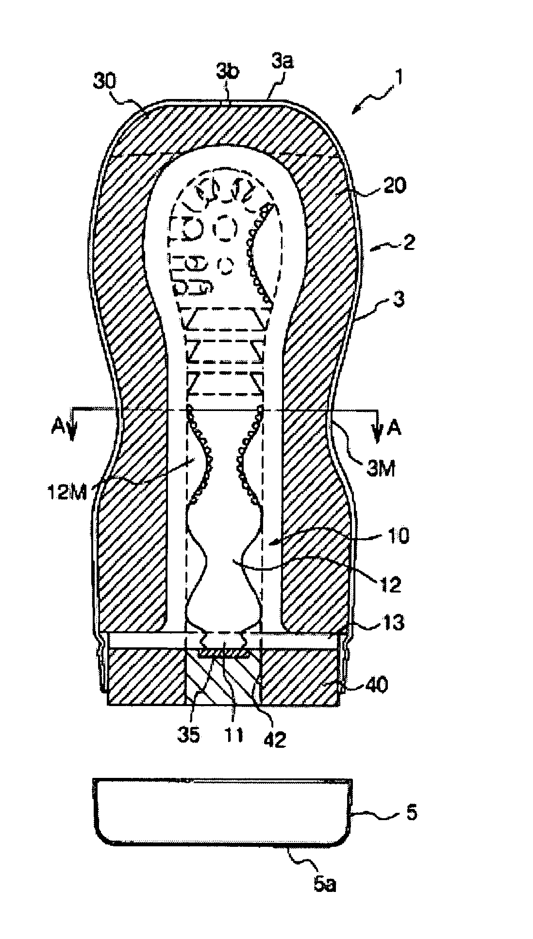
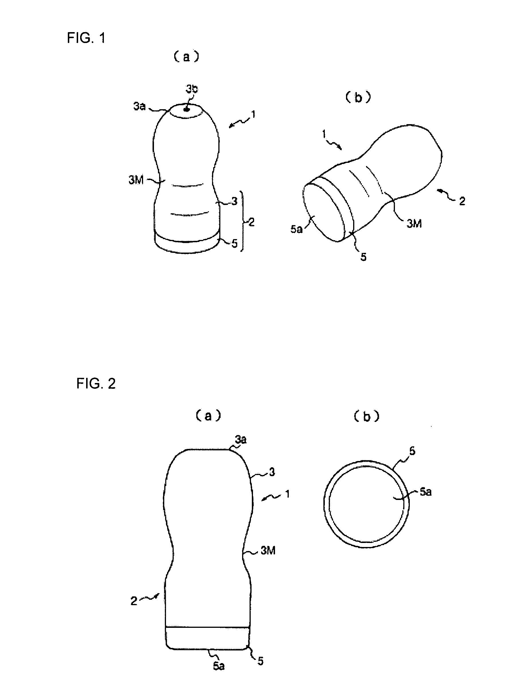
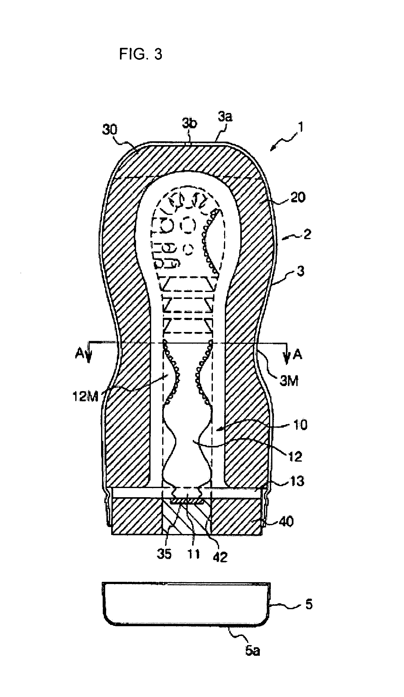
[0125] FIGS. 1(a) and 1(b) are appearance perspective views of a sperm collecting apparatus according to the present invention, FIGS. 2(a) and 2(b) are a front view and a bottom view of the sperm collecting apparatus, FIG. 3 is a vertical sectional view of the sperm collecting apparatus, FIGS. 4(a) and 4(b) are an exploded perspective view of respective constituent elements and an appearance perspective view of a core member, and FIG. 5 is a sectional view of the sperm collecting apparatus taken along line A-A in FIG. 3.

[0126] The sperm collecting apparatus 1 includes a container 2 having a non-cylindrical container main unit 3 whose one end face in a longitudinal direction thereof is opened and a cap 5 that is attached to and detached from an opening portion 4 of the container main unit 3 to open and close the opening portion, a core member 10 made from a gel-like resin, that is accommodated in the container main unit 3 and has an insertion room 12 extending from an insertion port ...

second embodiment

[0144] That is, FIGS. 6(a), 6(b) and 6(c) are a front view, a side view, and a perspective view showing a configuration of a sperm collecting apparatus according to the present invention, FIG. 7 is a vertical sectional view of the sperm collecting apparatus, and FIG. 8 is an exploded perspective view of respective constituent elements.

[0145] The most different point between the sperm collecting apparatus 1 according to this embodiment and the sperm collecting apparatus according to the above first embodiment lies in a shape of the container. The containers of the respective embodiments are the same in a point that the both are formed in non-cylindrical shape, but the container according to this embodiment is different from that according to the first embodiment in a point that the former container is formed in a circular shape at one end face thereof in the longitudinal direction while a width of a side face shape thereof gradually decreases toward the other end side thereof so that...

third embodiment

[0207] Next, a third embodiment will be explained in detail by embodiments shown in the drawings.

[0208]FIG. 18 is an appearance perspective view of a sperm collecting apparatus according to one embodiment of the third invention, FIGS. 19(a) and 19(b) are a front view and a bottom view of the sperm collecting apparatus, FIG. 20 is a vertical sectional view of the sperm collecting apparatus, FIGS. 21(a) and 21(b) are an exploded perspective view of respective constituent elements and an appearance perspective view of a core member, and FIG. 22 is a sectional view of the sperm collecting apparatus taken along line A-A in FIG. 20.

[0209] The sperm collecting apparatus 1 includes a container 2 having a non-cylindrical container main unit 3 whose both end faces in a longitudinal direction thereof are opened and caps 5a and 5b that are respectively attached to and detached from opening portions 4a and 4b of the container main unit 3 to close and open the opening portions, a core member 10 ...


PUM


Abstract

A sperm collecting apparatus is provided and includes a container having a non-cylindrical container main unit whose one end face in a longitudinal direction is open and a cap that is attachable the container main unit. A core member made from a gel-like material, which is located in the container main unit and has an insertion room extending to an inner portion of the core member from an insertion port at one end face in the core member. A sponge layer which is interposed between the core member and an inner wall of the container main unit, the container main unit is a non-cylindrical member whose intermediate portion in a longitudinal direction thereof has an outer diameter smaller than those in both end portions.

Description

TECHNICAL FIELD [0001] The present invention relates to a sperm collecting apparatus, and in particular relates to an improvement of conventionally-used sperm collecting apparatuses based on social demands, such as medical researches, demands for medical treatment, prevention of sex-related crime's, antiprostitution activities, and prevention of spreading of venereal diseases, and the like. BACKGROUND OF THE INVENTION [0002] Various sperm collecting apparatuses for collecting men's sperm have been proposed for necessities of medical research or treatment. For example, a sperm collecting apparatus is used for medical needs such as examination of sexual function of a husband from the sperm collected for examination of the cause of a marital infertility, or treatment of sexual dysfunction, and reservation and storage of the sperm for artificial insemination. Simple sperm collecting apparatuses that can be conventionally available at a low price and that do not cause sanitary or health ...

Claims


Application Information

Patent Timeline
Patent Type & Authority Applications(United States)
IPC IPC(8): A61F5/44
CPCA61B10/0045A61H19/32A61H9/005A61F5/453A61H19/00A61J1/05A61F6/04
Inventor MATSUURA, TSUTOMU
Owner TENGA
Why Eureka
Try Eureka