

Light source module and display device having the same
- Summary
- Abstract
- Description
- Claims
- Application Information
AI Technical Summary
Benefits of technology
Problems solved by technology
Method used
Image

Examples
first embodiment
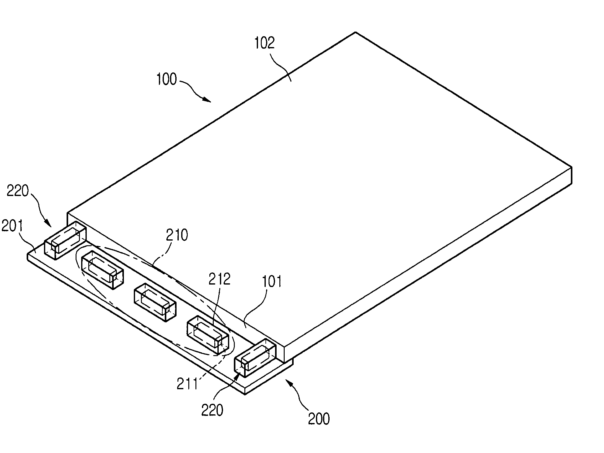
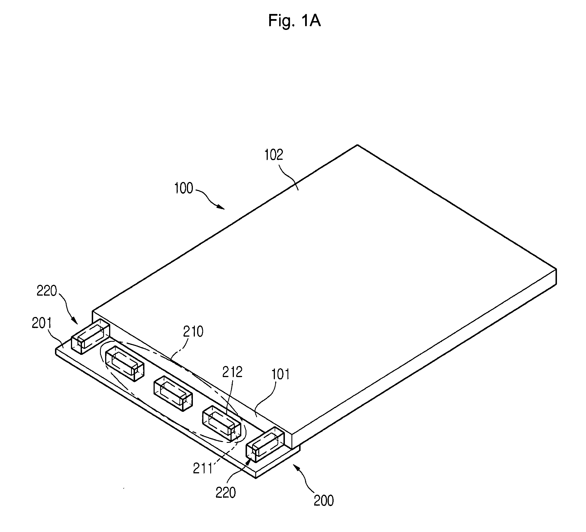
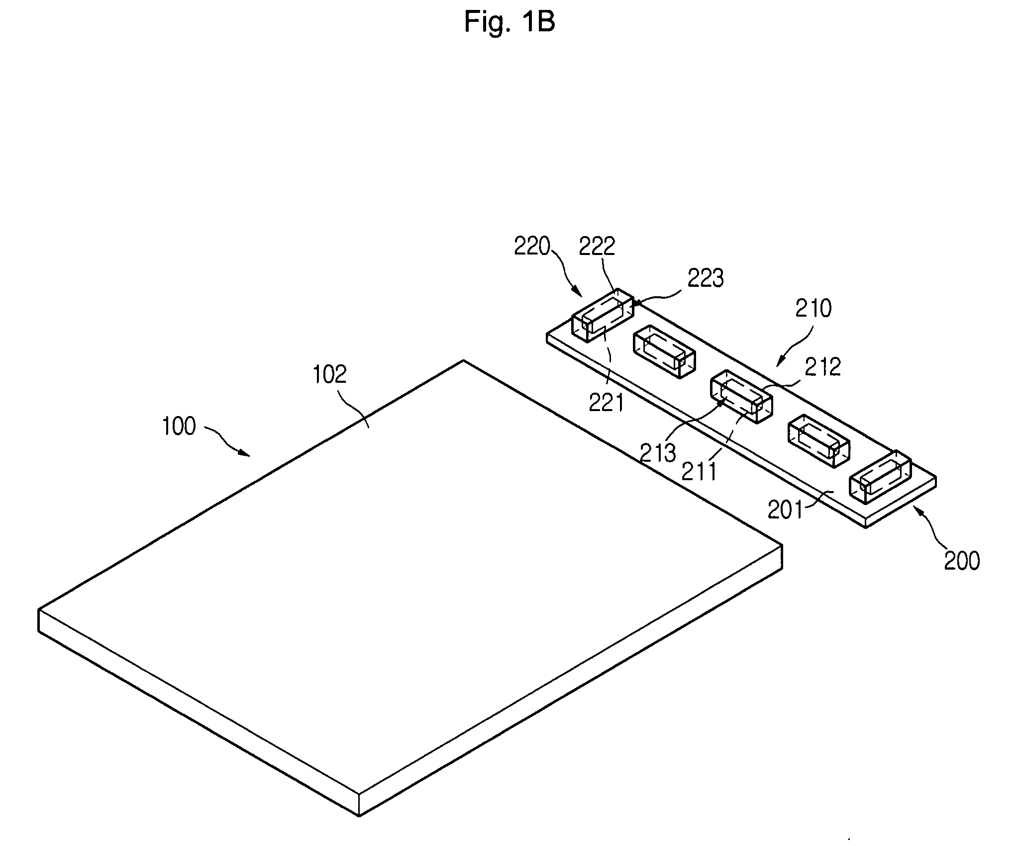
[0039]In this embodiment, the second light P2 emitted from the second light source 220 is reflected from the first light source 210 or the light source mounting surface 201 and then is provided to the dark spots of the light guide plate 100. In this way, the second light P2 is provided to a portion of the light guide plate 100 where the first light P1 is not provided, thereby reducing the brightness deviation of the light guide plate 100. In addition, since the second light source 220 secures and supports the light guide plate 100, a collision between the light guide plate 100 and the first light source 210 can be prevented. Therefore, the light source module according to the present invention requires no additional securing members.
[0040]FIGS. 2A to 2C illustrate a light source module according to a second embodiment of the present invention. Specifically, FIG. 2A is a perspective view of the light source module according to the second embodiment of the present invention, FIG. 2B i...
third embodiment
[0045]FIG. 3 is a perspective view of a light source module according to the present invention. The light source module shown in FIG. 3 has a structure substantially identical to that shown in FIGS. 2A to 2C, except for the use of a second light reflector 240 in addition to the first reflector 230. Duplicate description about the same components will be omitted for the purposes of conciseness and the same reference numbers and terms will be used to refer to the same components.
[0046]Referring to FIG. 3, the light source module includes a light guide plate 100, a board 200, a plurality of first light sources 210, a plurality of second light sources 220, a first light reflector 230, and a second light reflector 240 for reflecting light to the light guide plate. The second light reflector 240 faces a light source mounting surface 201 and is disposed on an edge of the first light reflector 230. The first light reflector 230 and the second light reflector 240 enclose the first and second...
PUM
 Abstract
Description
Claims
Application Information