A constant current drive circuit

A technology of constant current drive and circuit, applied in the direction of lamp circuit layout, electric light source, electrical components, etc., can solve problems such as dark brightness and poor display effect, achieve the goals of shortening the difference, optimizing display effect, and improving user experience Effect

Active Publication Date: 2018-12-28
SHENZHEN SUNMOON MICROELECTRONICS
View PDF5 Cites 0 Cited by
  • Summary
  • Abstract
  • Description
  • Claims
  • Application Information

AI Technical Summary

Problems solved by technology

[0015] The purpose of the embodiments of the present invention is to provide a constant current drive circuit, aiming to solve the problem of the actual brightness ratio setting of the LED due to the existence of the parasitic capacitance of the output current port in the existing constant current drive chip used to drive the LED to emit light. The brightness corresponding to the value is too dark, and the display effect is not good

Method used


Image

  • A constant current drive circuit
  • A constant current drive circuit
  • A constant current drive circuit

Examples


Embodiment 1

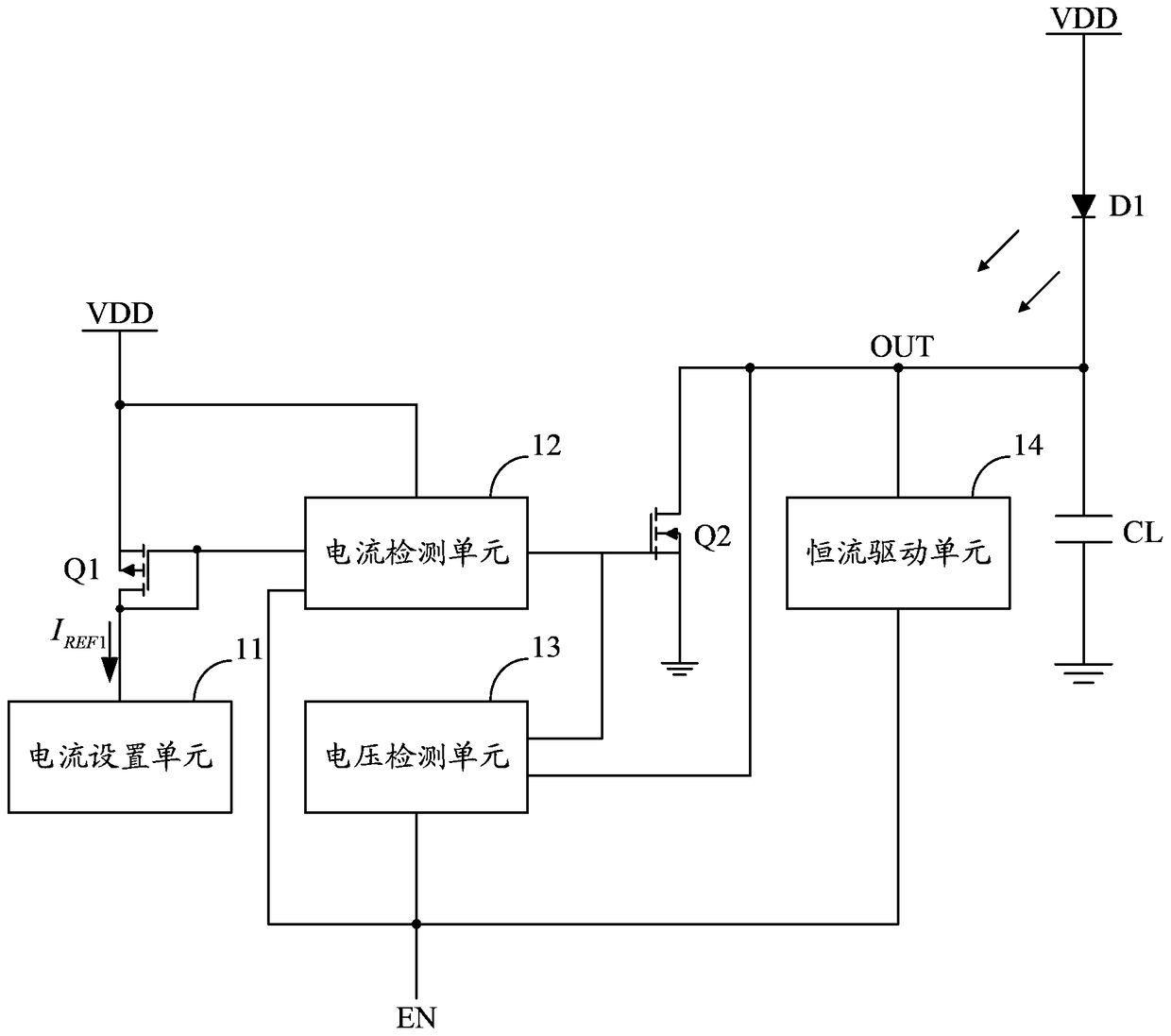
[0030] Embodiment 1 of the present invention proposes a constant current drive circuit, such as figure 2 As shown, for ease of description, only the part related to Embodiment 1 of the present invention is shown.

[0031] In detail, the constant current drive circuit proposed in Embodiment 1 of the present invention includes a power switch tube Q1 and a power switch tube Q2, the high end of the power switch tube Q1 is connected to the direct current VDD, and the driving end of the power switch tube Q1 is connected to the low voltage of the power switch tube Q1. end, the low end of the power switch tube Q2 is grounded; the constant current drive circuit also includes: a constant current drive unit 14, the input end of the constant current drive unit 14 is connected to the enable control signal EN, and the output terminal OUT of the constant current drive unit 14 serves as The output current port of the constant current drive circuit is connected to the drive terminal of the lo...

Embodiment 2

[0037] Embodiment 2 of the present invention proposes a constant current drive circuit, such as Figure 4 As shown, for ease of description, only the part related to Embodiment 2 of the present invention is shown.

[0038] In order to reduce the power consumption of the constant current drive circuit, it is expected that the current detection unit 12 will be turned off after the load is fully turned on. For this reason, different from the first embodiment, the constant current drive circuit provided by the second embodiment may also include: delayed shutdown Unit 15, the second input terminal of the current detection unit 12 is connected to the enabling control signal EN through the delay closing unit 15, the input terminal of the delay closing unit 15 is connected to the enabling control signal EN, and the output terminal of the delay closing unit 15 The second input end of the current detection unit 12 is connected, and is used for reducing the voltage value of the output cu...


PUM


Abstract

The invention belongs to the field of constant-current driving and provides a constant-current driving circuit. A current pre-opening technology is adopted in the constant-current driving circuit; parasitic capacitance is provided instantaneously when the circuit is opened, and flows through an electric energy discharging channel of a power switch pipe Q2, so that the voltage of an output current port of the constant-current driving circuit is quickly reduced to be output when load is completely conducted, the load quickly enters a complete conduction state, and the difference value between the effective conduction time of the load and the effective level time of an enable control signal is greatly shortened; when the load is an LED (light-emitting diode), the corresponding brightness deflection between the practical brightness of the load and set value output by an LED display screen controller is reduced, the displaying effect is optimized, and the user experience is improved.

Description

technical field [0001] The invention belongs to the field of constant current driving, and in particular relates to a constant current driving circuit which is mainly used to drive LEDs to emit light and can realize the function of current pre-opening. Background technique [0002] It is well known that in the field of LED display, in order to enhance the color authenticity of the low-gray-scale display of the LED display and the smoothness of the screen playback, in addition to a high refresh rate, it is also necessary to have the ability of high output color levels to express richer colors. display image of . For this reason, it is required that the luminous brightness of the LED in the LED display screen cannot be deviated when displaying the picture, and since the luminous brightness of the LED is determined by the average current passing through the LED, it is required that the average current output by the constant current driver chip that drives the LED to emit light ...

Claims


Application Information

Patent Timeline
Patent Type & Authority Patents(China)
IPC IPC(8): H02M1/36H05B37/02
Inventor 李照华陈克勇李国添陈艳霞符传汇石磊
Owner SHENZHEN SUNMOON MICROELECTRONICS
Why Eureka
Try Eureka