Engine power reduction during automatic transmission shifting

a technology of automatic transmission and engine power reduction, which is applied in hybrid vehicles, instruments, transportation and packaging, etc., can solve the problems of reducing the engine's power fully and reducing the engine's power, so as to reduce the power, reduce the engine's power, and reduce the effect of power

Inactive Publication Date: 2008-07-03
HONDA MOTOR CO LTD
View PDF17 Cites 5 Cited by
  • Summary
  • Abstract
  • Description
  • Claims
  • Application Information

AI Technical Summary

Benefits of technology

[0011]According to another embodiment of the invention, a method comprises the steps of providing a vehicle having an engine and an automatic transmission, gradually reducing the engine's power during a torque phase of a clutch-to-clutch up-shift within the automatic transmission, and reducing the engine's power fully at about the time that the clutch-to-clutch up-shift transitions from the torque phase to an inertia phase. The engine's power may be reduced substantially throughout the duration of the torque phase. Further, the engine's power may be increased at about the time that the inertia phase ends.
[0012]According to another embodiment of the invention, a vehicle may comprise an engine, an automatic transmission, and a control unit. The control unit may gradually reduce the engine's power during the torque phase of a clutch-to-clutch up-shift within the automatic transmission and may reduce the engine's power fully at about the time that the clutch-to-clutch up-shift transitions from the torque phase to an inertia phase. The automatic transmission may comprise at least a first and second hydraulic clutch.
[0013]One advantage of this invention is that it eliminates the “shift-shock” commonly felt by passengers in a vehicle that is caused by a complete reduction in engine power occurring prior to the transition from the inertia phase to the torque phase. Further, by completely reducing engine power at the transition from the inertial phase to the torque phase the ride comfort felt by the passenger is increased.
[0014]Another advantage of this invention is that it decreases the component wear on automatic transitions. A complete reduction of engine power that occurs after the transition from the inertia phase to the torque phase causes increased stress on the automatic transmission components.

Problems solved by technology

The control unit may gradually reduce the engine's power during the torque phase of a clutch-to-clutch up-shift within the automatic transmission and may reduce the engine's power fully at about the time that the clutch-to-clutch up-shift transitions from the torque phase to an inertia phase.

Method used


Image

  • Engine power reduction during automatic transmission shifting
  • Engine power reduction during automatic transmission shifting
  • Engine power reduction during automatic transmission shifting

Examples


Embodiment Construction

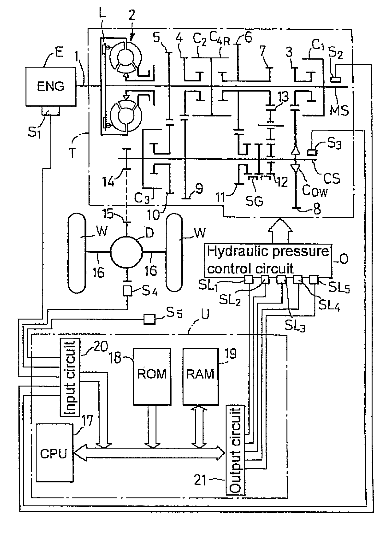
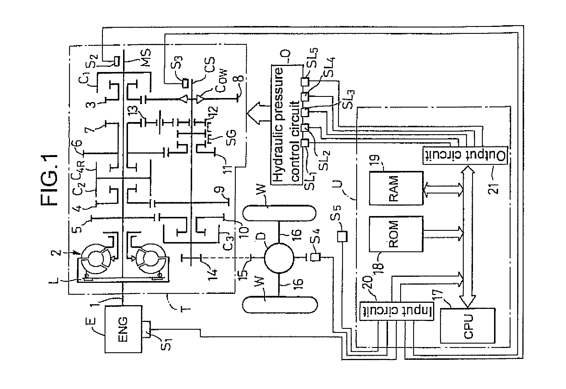
[0019]Referring now to the drawings wherein the showings are for purposes of illustrating embodiments of the invention only and not for purposes of limiting the same, FIG. 1 shows an automatic transmission T for a vehicle and includes a main shaft MS connected to a crankshaft 1 of an engine E through a torque converter 2 having a lock-up clutch L, and a counter shaft CS connected to the main shaft MS through a plurality of gear trains. The engine E may be a device designed to convert energy into mechanical force or motion. This invention will work with any engine chosen with sound engineering judgment. Non-limiting examples include internal combustion engines, external combustion engines, electric engines and hybrid engines that perform both as internal combustion engines and as electric engines. The automatic transmission T may be a device designed to transfer force between machines or mechanisms, often with changes in torque and speed, using at least one gear set and at least one ...


PUM


Abstract

An engine's power may be gradually reduced during a torque phase of a clutch-to-clutch up-shift within an automatic transmission and then reduced fully during a subsequent inertia phase.

Description

[0001]This application claims priority from U.S. Provisional Application No. 60 / 878,040, titled Method for Engine-Power Control Throughout Automatic-Transmission Clutch-to-Clutch Up-Shifting, filed Dec. 29, 2006, which is incorporated herein by reference.I. BACKGROUND OF THE INVENTION[0002]A. Field of Invention[0003]This invention pertains to the art of methods and apparatuses regarding vehicle automatic transmission systems, and more particularly to methods and apparatuses regarding engine power reduction during automatic transmission up-shifting.[0004]B. Description of the Related Art[0005]Automatic transmissions include a plurality of gears and associated components that are manipulated to drive an output shaft using different gear ratios. A transmission controller monitors vehicle operating conditions and driver input to determine whether an up-shift or a down-shift should occur. As is well known in the art, during an up-shift an on-coming component gradually engages a next gear...

Claims


Application Information

Patent Timeline
Patent Type & Authority Applications(United States)
IPC IPC(8): B60K6/20F16H59/14G06F19/00
CPCB60W10/06B60W10/11B60W30/19B60W2710/0605Y10T477/67F16H63/502F16H2061/0492Y10T477/677F16H61/061
Inventor DICKINSON, MIKE
Owner HONDA MOTOR CO LTD
Why Eureka
Try Eureka