Compact antenna

a compact antenna and antenna technology, applied in the field of antennas, can solve the problem of not preventing wide band operation, and achieve the effect of reducing the antenna reflection coefficient and improving the antenna performan

Active Publication Date: 2008-07-31
GALTRONICS USA INC
View PDF22 Cites 196 Cited by
  • Summary
  • Abstract
  • Description
  • Claims
  • Application Information

AI Technical Summary

Benefits of technology

[0017]Both the feed region and the coupling region are typically close to a common edge of the ground plane. Alternatively, one or both of the regions may be indented from the edge, in which case the monopole and / or the coupling element may be correspondingly extended. In a disclosed embodiment, a length of an indentation, and of a corresponding section of the coupling element within the indentation, is adjusted to improve performance of the antenna by reducing the antennas reflection coefficient. In some disclosed embodiments, the indentation is configured to have more than one direction, for example by being formed in the shape of an “L,” the different directions providing control for directions of polarization of radiation from the antenna. The polarization may be further controlled by selecting whether the section of the coupling element galvanically or capacitively couples to the ground plane. Alternatively or additionally, polarization may be controlled by locating the coupling region along an edge of the ground plane different from the edge close to the feed region.

Problems solved by technology

A narrow bandwidth of the coupling element does not prevent wide band operation, if the center frequencies of the coupling element and the ground plane are relatively close together.

Method used


Image

  • Compact antenna
  • Compact antenna
  • Compact antenna

Examples


Embodiment Construction

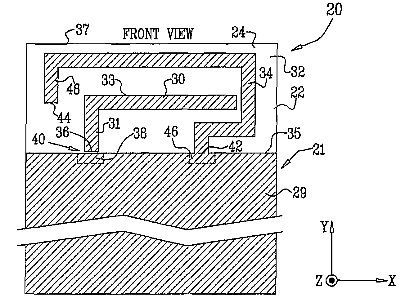
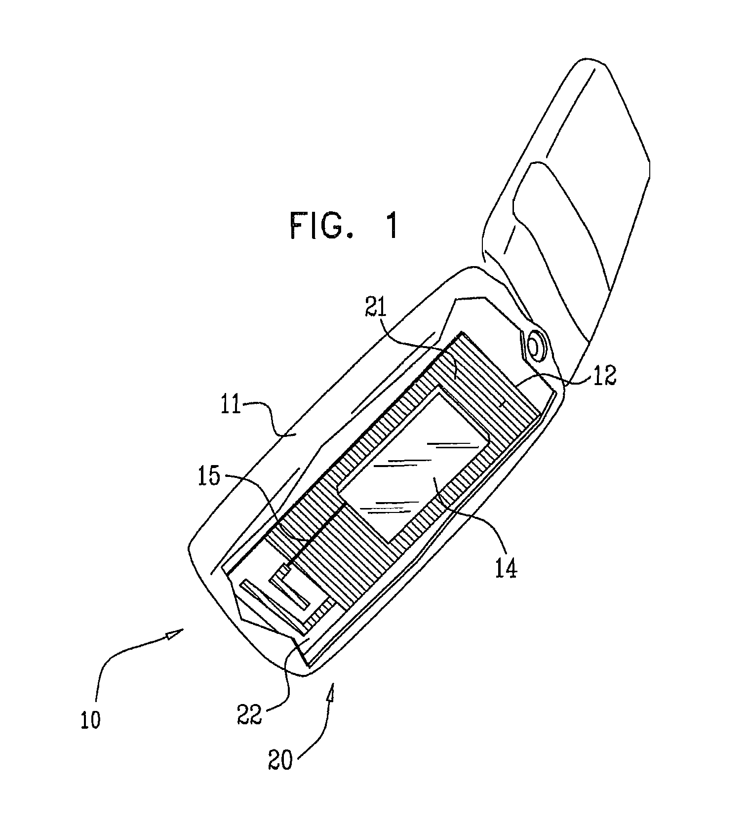
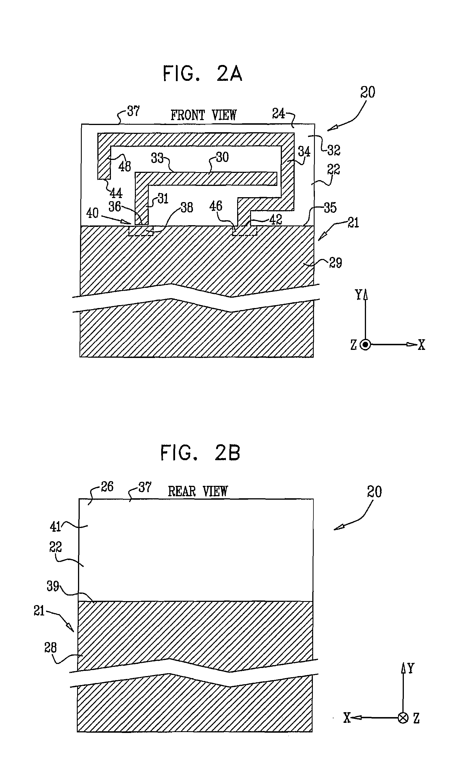
[0150]Reference is now made to FIG. 1, which is a schematic diagram of a communication device 10, according to an embodiment of the present invention. Device 10 is typically a cellular phone or a personal digital assistant (PDA), and the device is hereinbelow assumed to comprise a cellular phone. Phone 10 has an enclosure 11, within which operational elements of the phone are mounted. Phone 10 comprises a transceiver 14 which is mounted on a dielectric substrate 22. Typically, substrate 22 is a planar dielectric substrate for a multilayer printed circuit board (PCB) 12, and components of transceiver 14 are mounted on the substrate. In some embodiments of the present invention, substrate 22 may comprise one or more dielectric layers of multilayer PCB 12, and other dielectric layers of the multi-layer PCB may be located above and / or below substrate 22. For clarity, such other layers are not shown in FIG. 1. It will be understood that substrate 22 may comprise dielectrics other than th...


PUM

PropertyMeasurementUnit
frequenciesaaaaaaaaaa

Abstract

An antenna, including a planar dielectric substrate and a conductive ground plane formed on the substrate. A conductive monopole is formed on the substrate and has an end point located in proximity to a feed region of the ground plane. A conductive coupling element is formed on the substrate and is coupled to the ground plane at a coupling region of the ground plane. The coupling element is folded around the monopole.

Description

CROSS-REFERENCE TO RELATED APPLICATION[0001]This application claims the benefit of U.S. Provisional Patent Application 60 / 859,629, filed 16 Nov. 2006, which is incorporated herein by reference.FIELD OF THE INVENTION[0002]The present invention relates generally to antennas, and specifically to antennas that may be used in multiple bands.BACKGROUND OF THE INVENTION[0003]As the size of communication devices, such as cellular telephones, is reduced, typically the size of the antenna is required to be reduced as well. However, basic properties of the antenna may limit the freedom that a designer has to reduce the size of the antenna without adversely affecting the overall antenna performance. A paper titled “Introduction to Ultra-Wideband Antennas,” by Schantz, presented at the IEEE Conference on Ultra Wideband Systems and Technologies, November, 2003, describes some of the limitations that the author believes may hold for antennas. The paper is incorporated herein by reference.[0004]The...

Claims


Application Information

Patent Timeline
Patent Type & Authority Applications(United States)
IPC IPC(8): H01Q1/50H01P11/00H01Q9/04H01Q5/10H01Q5/371H01Q5/385
CPCH01Q1/243H01Q1/38H01Q5/385Y10T29/49016H01Q5/371H01Q9/42H01Q1/24H01Q9/04H01Q9/30H01Q5/10
Inventor MARTISKAINEN, MATTICHO, DANIELKRUPA, STEVEAZULAY, SNIRHAIM, YONA
Owner GALTRONICS USA INC
Why Eureka
Try Eureka