Thermal erosion test device and method for testing thermal protection materials of solid propellant thrusters

a technology of thermal protection materials and test devices, which is applied in the direction of engine fuction, material thermal analysis, structural/machine measurement, etc., can solve the problems of inability to use the model available for thermal erosion calculation and inability to devise a calculation model, so as to preserve the stress level

Active Publication Date: 2008-08-14
ARIANEGRP SAS +1
View PDF10 Cites 8 Cited by
  • Summary
  • Abstract
  • Description
  • Claims
  • Application Information

AI Technical Summary

Benefits of technology

[0010]The test device of the present invention thus makes it possible to expose a plate of thermal protection material to a tangential flow of combustion gas generated by a block of propellant placed facing said plate. This configuration makes it possible to carry out tests under conditions that are close to those of 1 / 1 scale. The Applicant has found that using a plane plate for the material under test in a device defining a flow stream that is of substantially rectangular section and that extends along the plate makes it possible to reproduce conditions that are close to those encountered by internal thermal protection in thrusters, in particular because of the fact that radii of curvature are large at 1 / 1 scale.
[0017]The measurements collected with such instrumentation can be used for accurately characterizing the thermal erosion behavior of the material under test, to define conditions for subsequent tests by adjusting stress levels, and to devise calculation methods for use in dimensioning thermal protection at 1 / 1 scale.
[0018]According to yet another aspect of the invention, the test device includes means for adjusting the distance between the block of solid propellant and the plate of thermal protection material for testing. In this way, the levels of aerothermal stresses within the device can be set merely by adjusting the height of the combustion chamber, thus making it possible in particular to conserve a level of stress that is similar from one test firing to another by setting the operating pressure by means of the diameter of the throat of the nozzle.
[0019]The thermal erosion test device of the present invention further includes a cylindrical shell having an inside volume in which the plate of thermal protection material for testing and the block of solid propellant are placed. Thus, by taking the assembly of rectangular shape made up of the plate of material for testing and the block of propellant, and placing said assembly within a shell that is cylindrical in shape, it is possible to establish operating pressures that are representative of the operating range of thrusters at 1 / 1 scale. Obtaining such pressure levels with a purely rectangular shape would require metal plate thicknesses for withstanding pressure forces that are unacceptable, whether in terms of weight or in terms of cost. The use of a shell in accordance with the invention gives the setup an outside shape that is cylindrical, thereby enabling the pressure forces generated therein to be distributed uniformly, and thus enabling it to be placed in a metal tube of reasonable thickness.

Problems solved by technology

Either way, the model available for thermal erosion calculation is not usable since it is based on an erosion criterion defined from a specific material.
Although such tests make it possible to carry out comparative studies between two materials, they are not representative of behavior at 1 / 1 scale, and consequently they cannot be used for devising a calculation model that can be used for evaluating and dimensioning thermal protection for use in a thruster at 1 / 1 scale.

Method used


Image

  • Thermal erosion test device and method for testing thermal protection materials of solid propellant thrusters
  • Thermal erosion test device and method for testing thermal protection materials of solid propellant thrusters
  • Thermal erosion test device and method for testing thermal protection materials of solid propellant thrusters

Examples


Embodiment Construction

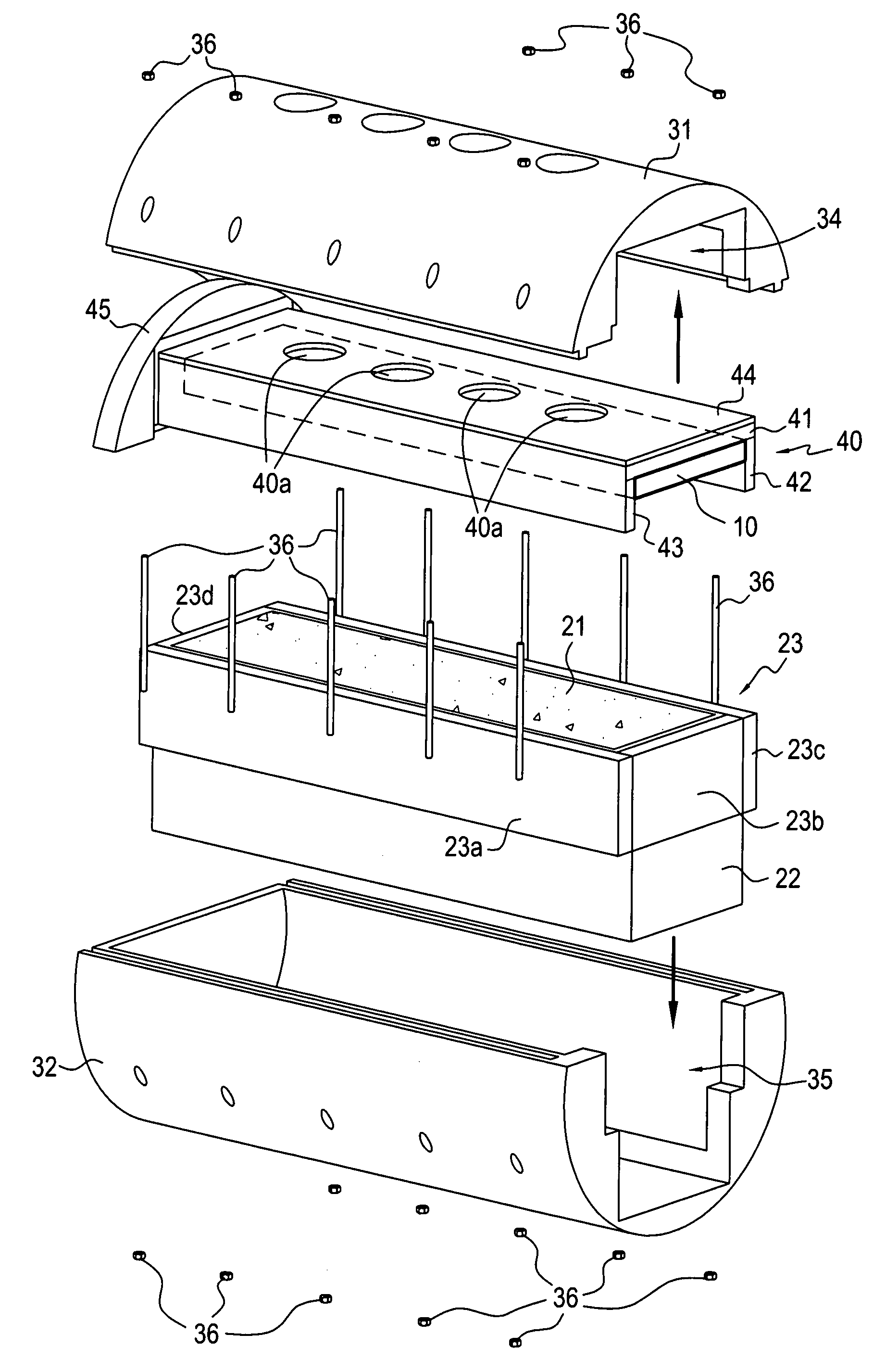
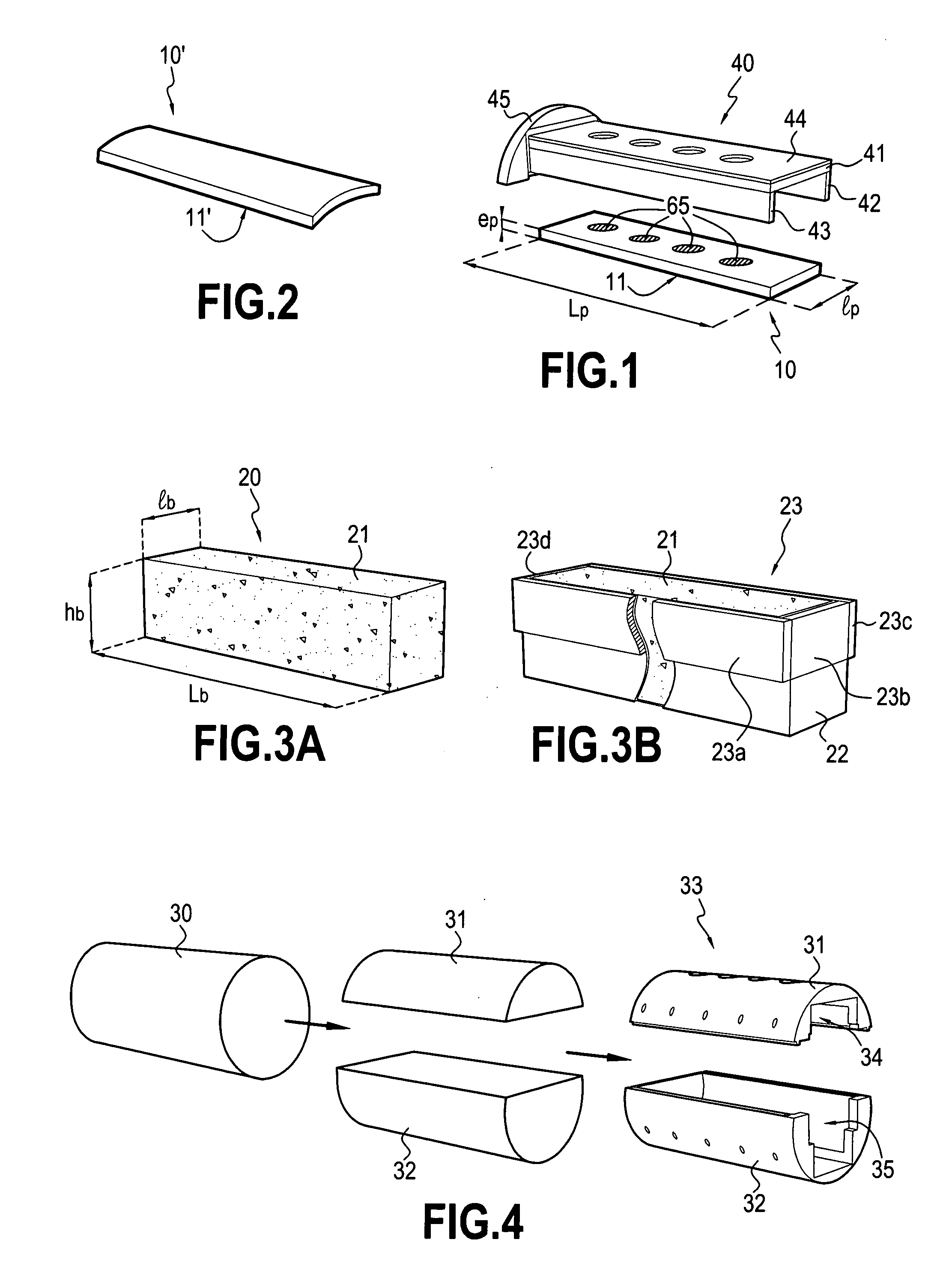
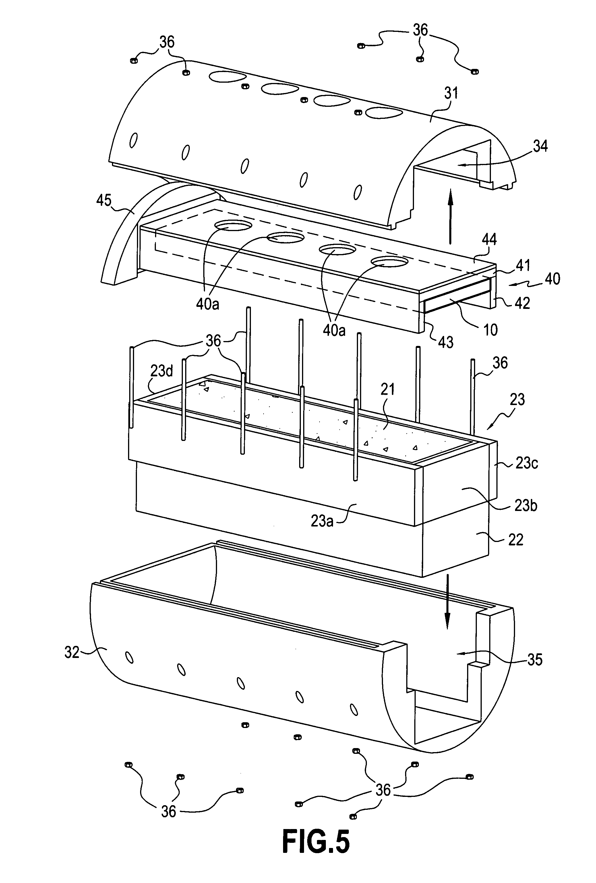
[0032]The principle of the thermal erosion test device of the present invention is to subject a sample of thermal protection material to a tangential flow of combustion gas generated by a rectangular block of solid fuel placed facing the sample.

[0033]According to an aspect of the invention, the sample of thermal protection material for testing is made in the form of a plate. FIG. 1 shows a plate thermal protection material 10 forming the sample of thermal protection material for testing in the device of the invention. The plate 1 is preferably of a shape that is sufficiently plane to approximate to the large radii of curvature that are to be encountered in thrusters at 1 / 1 scale. This plane shape is the simplest to make and makes it easier to incorporate measurement means as described below and also easier to run the test. Nevertheless, as shown in FIG. 2, the plate 10′ of thermal protection material may equally well present a small amount of curvature. In general, the face 11 (or 1...


PUM

PropertyMeasurementUnit
diameteraaaaaaaaaa
widthaaaaaaaaaa
widthaaaaaaaaaa

Abstract

The invention relates to a thermal erosion test device for testing thermal protection materials for use in a solid propellant thruster. The device comprises a support for holding a plate made of the thermal protection material for testing so that its faces a face of a block of solid propellant, the space between the plate and the face of the propellant block defining a combustion chamber of substantially rectangular shape, said chamber extending along said plate and opening out into a nozzle.

Description

BACKGROUND OF THE INVENTION[0001]The present invention relates to the field of thermal protection materials for use in solid propellant thrusters. More precisely, the invention relates to tests and modeling means suitable for characterizing the thermal erosion behavior of thermal protection made using such materials under conditions that are representative of those to which they will be subjected in a full-sized thruster, i.e. at 1 / 1 scale.[0002]The performance of thermal protection is evaluated as a function of its thermal erosion behavior in response to the gas generated by the combustion of the solid propellant. During combustion of the propellant in the thruster, under the effect of the high temperatures those portions of the thermal protection material that are exposed to the flow of combustion gas become degraded on the surface by forming coke, and the coke as formed in this way is subjected to erosion to a greater or lesser extent as a function of the degree of its exposure t...

Claims


Application Information

Patent Timeline
Patent Type & Authority Applications(United States)
IPC IPC(8): G01N25/00G01M99/00
CPCF02K9/96G01N3/567F05D2250/22G01N2291/02881F05D2260/80G01N3/60
Inventor DEOCLEZIAN, JEAN-MARCPLAZANET, FREDERICNGUYEN, CAROLINEBODART, VINCENT
Owner ARIANEGRP SAS
Why Eureka
Try Eureka