Core Biopsy Device with Specimen Length Adjustment

a biopsy device and specimen technology, applied in the field of core biopsy devices with specimen length adjustment, can solve the problems of small core biopsy relative, increased damage to remaining tissue, and sample is not truly a full core sampl

Inactive Publication Date: 2008-11-13
INRAD
View PDF54 Cites 51 Cited by
  • Summary
  • Abstract
  • Description
  • Claims
  • Application Information

AI Technical Summary

Benefits of technology

[0016]In still another embodiment, the invention relates to a biopsy device for the percutaneous removal of a specimen from a tissue mass. The biopsy device comprises a housing having opposing sides, a needle assembly carried by the housing and comprising a stylet having a distal tip and a cannula defining a lumen for receiving the stylet, a firing assembly carried by the housing and operably coupled to the needle assembly to effect the relative movement of the cannula and the stylet to obtain a specimen, and a trigger assembly operably coupled to the firing assembly to control the actuation of the firing assembly and having a release button on each opposing side of the housing, wherein pressing either release button effects the actuation of the firing assembly.

Problems solved by technology

The disadvantage of this method is that it produces a small core biopsy relative to the outer cannula size since the cross section of the sample is substantially equal to the cross section of the stylet notch, which is substantially smaller than the cross section of the outer cannula.
The disadvantage of this full core device is that the end of the sample is not positively severed from the tissue mass, creating the possibility that the biopsy sample will be pulled out of the coring cannula upon the withdrawal of the coring cannula.
This can happen if the forces holding the sample in the coring cannula are not sufficient to tear the end of the sample from the tissue mass.
However, if these forces are not sufficient to tear the end of the sample from the tissue mass, the sample will be pulled out of the coring cannula upon the removal of the coring cannula.
However, this is not preferred as it increases the damage to the remaining tissue.
A disadvantage of this method is that the sample is not truly a full core sample since part of the interior of the cannula was reserved for the raceway.
If the sample produced by the cannula with the raceway was the same size as the full core sample, the cannula with the raceway would require a larger cross sectional cannula, which is not desirable.
The internally severing devices have the disadvantage in that the resulting sample is shorter in length than the amount of tissue that is received within the interior since the finger enters the coring cannula proximal to the coring cannula tip.
This is made more difficult in that the practitioner cannot use the end of the cannula for marking the extent of the biopsy specimen.
The disadvantage of this structure is that the coring and cutting cannulae are made from multiple pieces and include built in stops, which increase the assembly requirements and cost of the device.
Another disadvantage of all of the full core devices is that they rely on the relative movement between the coring cannula and the stylet to expel the sample from the interior of the coring cannula.
The use of the stylet to force out the sample can damage the sample.
The damage can be great enough to render the sample unsuitable for testing.
This can be very detrimental since some lesions being sampled are small enough that the entire lesion is contained within the sample.
This practice increases the invasiveness of the procedure and the pain to the patient.

Method used


Image

  • Core Biopsy Device with Specimen Length Adjustment
  • Core Biopsy Device with Specimen Length Adjustment
  • Core Biopsy Device with Specimen Length Adjustment

Examples


second embodiment

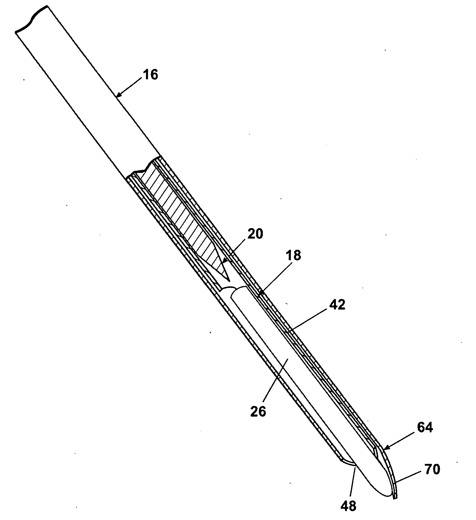
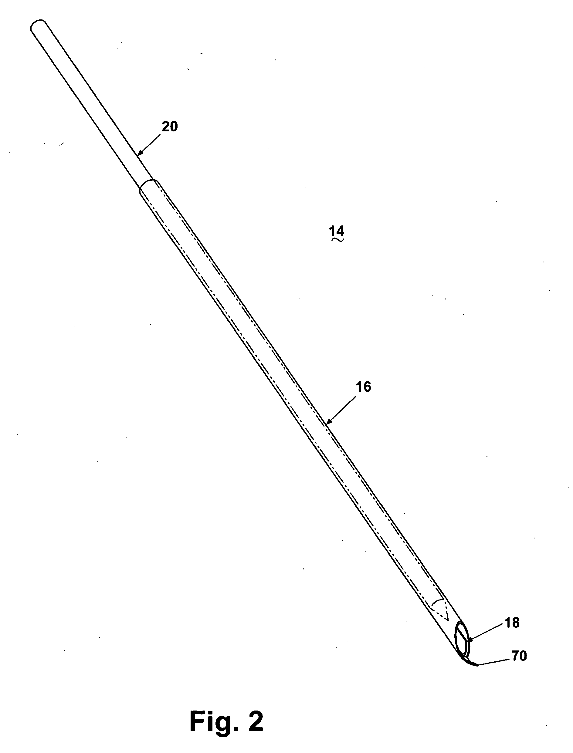
[0142]FIG. 10 illustrates the spoon cannula 18 in which the spoon section 42 is provided with an excising finger window 80 adjacent the insertion tip 48. The excising finger window 80 is a generally rectilinear opening in the arcuate wall 46 comprising a pair of parallel, spaced-apart longitudinal edges 82 defining a window width 84 adapted for slidable insertion of the excising finger 70. The excising finger window 80 has a distal edge 86 adjacent the insertion tip 48. The spoon cannula 18 is received as previously described in the lumen 76 for slidable movement of the spoon cannula 18 relative to the coring cannula 16.

first embodiment

[0143]The excising finger 70 is adapted for insertion through the excising finger window 80 so that the excising finger 70 bears against the distal edge 86. As the spoon cannula 18 is drawn into the coring cannula 16, the distal edge 86 bearing against the excising finger 70 will urge the excising finger 70 radially inwardly toward the longitudinal axis 76. Conversely, as the spoon cannula 18 is moved distally along the lumen 76, the finger 70 will resiliently return to its at-rest position. Because the distal edge 86 deflects the excising finger 70, the curvature of the excising finger 70 in its at-rest position can be much shallower, even approaching a straight line, thereby facilitating penetration of the excising finger 70 into the tissue 22 and the lesion 24. With a shallower curvature, the excising finger 70 will be less likely to deflect laterally during penetration. The deflection of the excising finger 70 by the movement of the spoon cannula 18 will enable the excising fing...

third embodiment

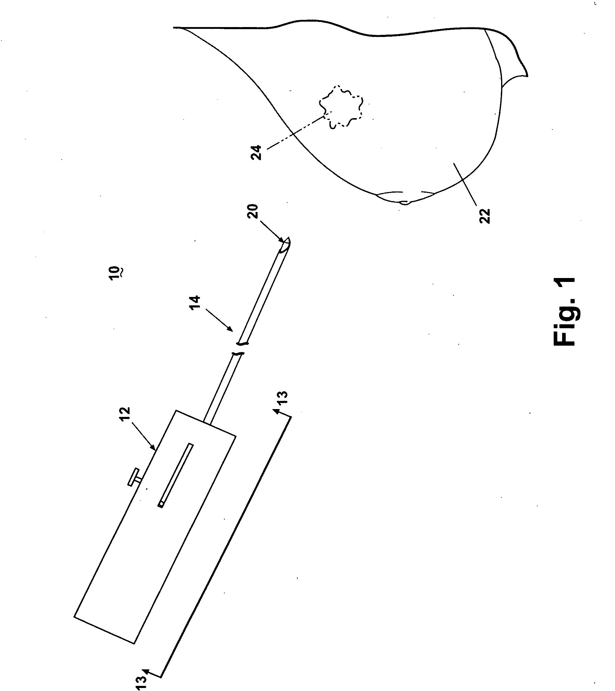
[0250]FIGS. 57-86 illustrate an actuator assembly or biopsy gun 1230 for both translating the cannula assembly 14 to the excising position and then rotating the coring cannula 16. FIG. 57 illustrates the biopsy gun 1230 operably connected to the cannula assembly 14. The actuator assembly 12 has a distal end 1232, a proximal end 1234, a dorsal side 1236 supporting a cocking handle assembly 1238, and a ventral side 1240.

[0251]The biopsy gun 1230 comprises an outer housing 1242 providing an ergonomic, functional handle for facilitating the insertion of the cannula assembly 14 in a lesion 24 and the recovery of a biopsy sample 26, and comprising a left housing shell 1244 and a right housing shell 1246 adapted for cooperative registry, each housing shell 1244, 1246 having a corresponding overmolded portion 1248, 1250 for providing a soft gripping surface on the housing 1242. The housing shells 1244, 1246 are provided with a suitable number of connecting elements, such as snap-fit retaine...


PUM


Abstract

A biopsy device comprises a housing carrying a stylet is telescoping register with a coring cannula and a specimen length adjuster operably coupled to the stylet to move the stylet relative to the coring cannula to set the size of the biopsy sample to be collected. The coring cannula is moved over the stylet and rotated relative to the stylet to excise the biopsy sample from surrounding tissue. A trigger assembly is provided that includes a release button on opposing sides of the housing as well as a rear trigger button that enables a user to comfortably actuate the biopsy device using any of the three trigger buttons.

Description

CROSS-REFERENCE TO RELATED APPLICATION[0001]This application is a continuation-in-part of U.S. application Ser. No. 10 / 908,427, filed May 11, 2005, which claims the benefit of U.S. provisional application No. 60 / 521,518, filed May 11, 2004, both of which are incorporated herein in their entirety.BACKGROUND OF THE INVENTION[0002]It is frequently necessary to sample or remove a sample from a suspect tissue for testing. In humans, such a sample removal is particularly useful in the diagnosis and treatment of cancerous or pre-cancerous conditions. In the case of suspected cancer, particularly cancer of the breast, early detection and diagnosis is critical to the success of the patient's treatment and recovery.[0003]Various techniques are available to aid in detection and diagnosis, including physical examination and imaging, such as mammography, x-ray, ultrasound, magnetic resonance imaging (MRI), and the like. When a condition is detected that suggests the possibility of cancer, a biop...

Claims


Application Information

Patent Timeline
Patent Type & Authority Applications(United States)
IPC IPC(8): A61B10/02
CPCA61B10/02A61B10/0266A61B10/0275A61B2010/0208A61B2010/045A61B2017/32004A61B2019/304A61B2090/034
Inventor PETERS, STEPHEN F.
Owner INRAD
Why Eureka
Try Eureka