Exhaust Gas System

Active Publication Date: 2008-11-27
FRIEDRICH BOYSEN +1
View PDF5 Cites 13 Cited by
  • Summary
  • Abstract
  • Description
  • Claims
  • Application Information

AI Technical Summary

Benefits of technology

[0018]The exhaust gas paths from the respective exhaust gas outlet up to the joining together are preferably each at least approximately of the same length. A crosstalk effect approximately the same for all cylinders is thereby effected.
[0019]In another advantageous embodiment of the invention, the combined exhaust ga

Problems solved by technology

These thermal expansions cause unwanted strains due to the rigid connection of the exhaust gas guidance elements and said strains can put a gre

Method used


Image

  • Exhaust Gas System
  • Exhaust Gas System
  • Exhaust Gas System

Examples


Embodiment Construction

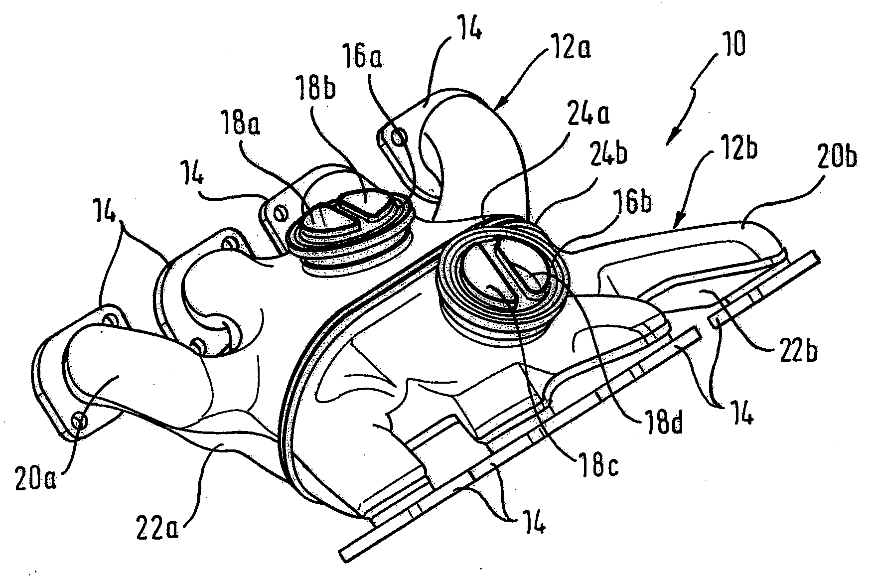
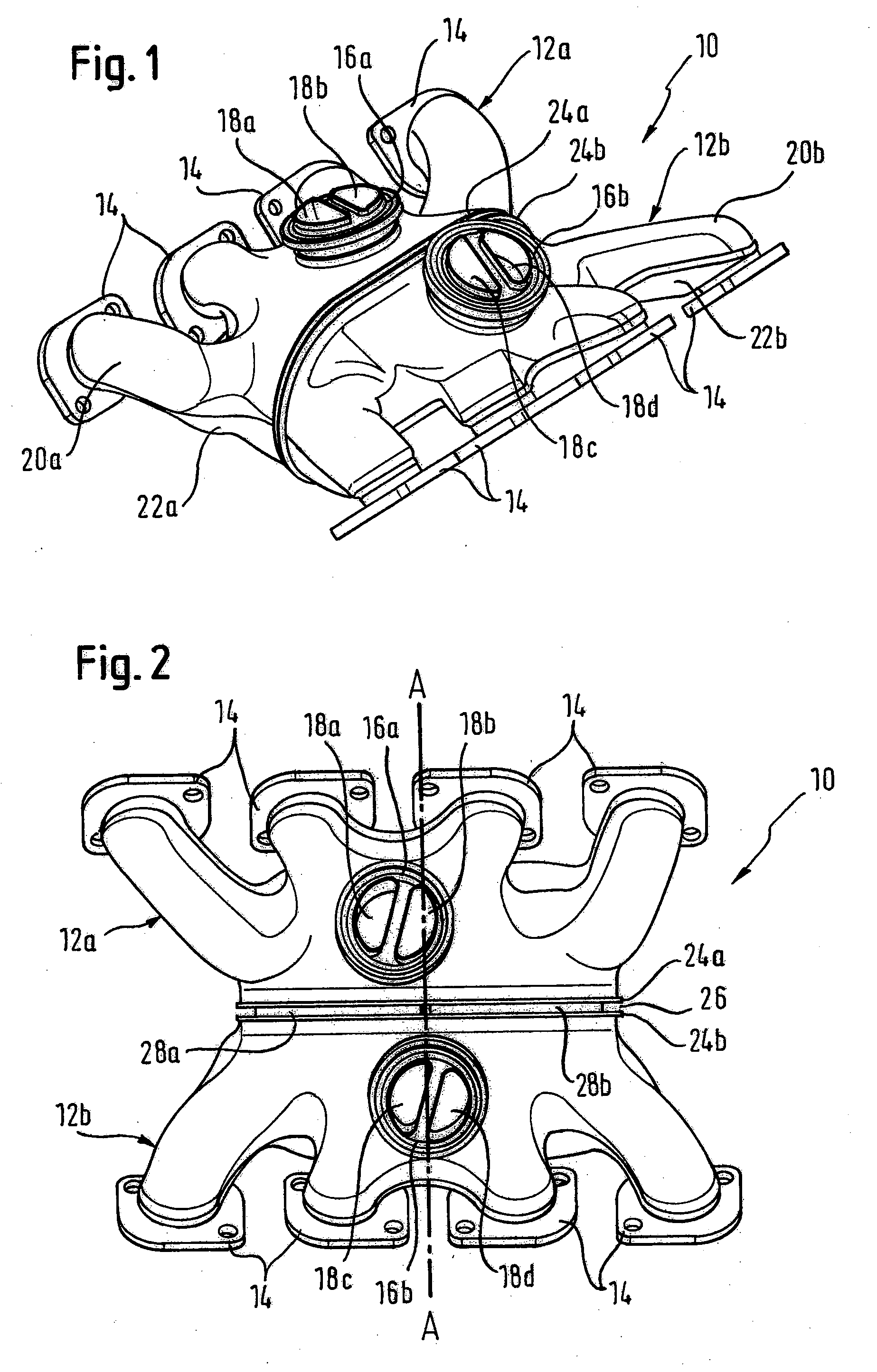
[0026]FIGS. 1 and 2 show a housing 10 of an exhaust gas system in accordance with the invention for an internal combustion engine which has two cylinder banks which are not shown here, which are arranged at an acute angle to one another and which each have four exhaust gas outlets. The housing 10 includes two housing parts 12a, 12b of which each one respectively includes four flanges 14 arranged in a row for the connection to the exhaust gas outlets of a cylinder bank. The two rows of flanges 14 accordingly face in opposite directions.

[0027]Each housing part 12a, 12b has an exhaust gas outlet opening 16a and 16b respectively which is provided for connection to following elements, not shown, of the exhaust gas system, for example to an exhaust gas turbocharger or to an exhaust gas purification system. Two exhaust gas collection devices 18a, 18b and 18c, 18c respectively, which are arranged mainly in the interior of the housing parts 12a, 12b and which are in turn connected to exhaust...


PUM


Abstract

An exhaust gas system for an internal combustion engine, in particular a motor vehicle engine, is provided having, in one form, two cylinder banks arranged at an acute angle to one anther and each having at least one exhaust gas outlet, a so-called V-engine, having exhaust gas guide elements arranged in the region of the inner angle, including a housing surrounding the exhaust gas outlets of both cylinder banks in a gas tight manner and having at least one exhaust gas outlet opening is characterized in that the housing is made in two parts, with a first part which is connected to the one cylinder bank and surrounds its exhaust gas outlets and with a second part which is connected to the other cylinder bank and surrounds its exhaust gas outlets; in that the two parts each have a side facing the other part and having at least one housing opening via which the two parts communicate with one another; and in that an expansion compensation element is arranged between the two parts and surrounds the housing opening of the two parts in a gas tight manner.

Description

FIELD OF THE INVENTION [0001]The present invention relates to an exhaust gas system for an internal combustion engine, in particular a motor vehicle engine, having two cylinder banks arranged at an acute angle to one anther and each having at least one exhaust gas outlet, a so-called V-engine, having exhaust gas guide elements arranged in the region of the inner angle, including a housing surrounding the exhaust gas outlets of both cylinder banks in a gas tight manner and having at least one exhaust gas outlet opening.BACKGROUND OF THE INVENTION [0002]The exhaust gas system serves for the leading away of the hot combustion gases arising in the internal combustion engine and is flanged directly to the corresponding outlets of the internal combustion engine. The housing surrounds the outlets of both cylinder banks in a gas tight manner. A connection is thereby possible between the outlets of the one cylinder bank and the outlets of the other cylinder bank in order also to enable cross...

Claims


Application Information

Patent Timeline
IPC IPC(8): F01N7/10F01N13/10F01N13/08
CPCF01N13/102F01N13/107F02B75/22
Inventor DIEZ, RAINERRAMUSCH, MARCUSSAHAN, RAMAZANVERDOORN, WERNER
Owner FRIEDRICH BOYSEN
Why Eureka
Try Eureka