Variable speed printing device with mains overload prevention

a printing device and variable speed technology, applied in the direction of optics, other printing devices, electromagnetography/magnetography, etc., can solve the problems of real limitation of electrical processes, power consumption, and inability to draw enough power from a wall socket or a group of wall sockets, so as to increase processing speed, reduce process speed, and maintain performan

Inactive Publication Date: 2008-12-11
OCE TECH
View PDF4 Cites 20 Cited by
  • Summary
  • Abstract
  • Description
  • Claims
  • Application Information

AI Technical Summary

Benefits of technology

[0013]In accordance with the above-described aspects of the invention, when during operation of the device the mains voltage sinks, the current drawn by the device, and especially the heaters of the fuser system, initially increases in order to maintain the performance. However, when the current drawn from the net increases too much, the control unit decreases the process speed, and in reaction, the power usage sinks as well, and the current comes back to its normal value. Preferably, the adjustment of the processing speed is done in an iterative process of small steps, such that after each step the effect is first assessed, before any new step is made. Moreover, in accordance with an important aspect of the invention, the processing speed is gradually adjusted from step to step. In this way, it is possible to change the processing speed while the process is running and sheets of image support material, such as paper sheets, are moving through the device. If the speed would be changed in discrete steps, the sheets would be torn or wrinkled by the sudden and local transport speed changes.
[0014]If the total electrical current drawn by the device is or comes below the preset maximum value, the processing speed is again increased. The speed may be increased to either the nominal processing speed value of the device, or to a speed corresponding to the preset current maximum value, if that is still below the nominal processing speed. In this way, maximal advantage is taken of the available mains power.
[0015]In a further embodiment, the preset current maximum value is in fact a current value range. In this way, frequent speed changes are prevented.
[0016]In yet a further embodiment, the preset maximum value is a pre-programmed function of time. In this way, a temporarily higher acceptable loading of the power net can be taken advantage of.

Problems solved by technology

The power that can be drawn from a wall socket or group of wall sockets is limited.
The initial speed is so high that the heater in the fuser roll cannot deliver enough heat to keep the fuser rolls at their operating temperature.
However, the real limitation of electrical processes is power consumption in relation to load limitation of the power net.

Method used


Image

  • Variable speed printing device with mains overload prevention
  • Variable speed printing device with mains overload prevention
  • Variable speed printing device with mains overload prevention

Examples


Embodiment Construction

[0030]The Figures are diagrammatic and not drawn to scale. In the Figures, elements that correspond to elements already described have the same reference numerals.

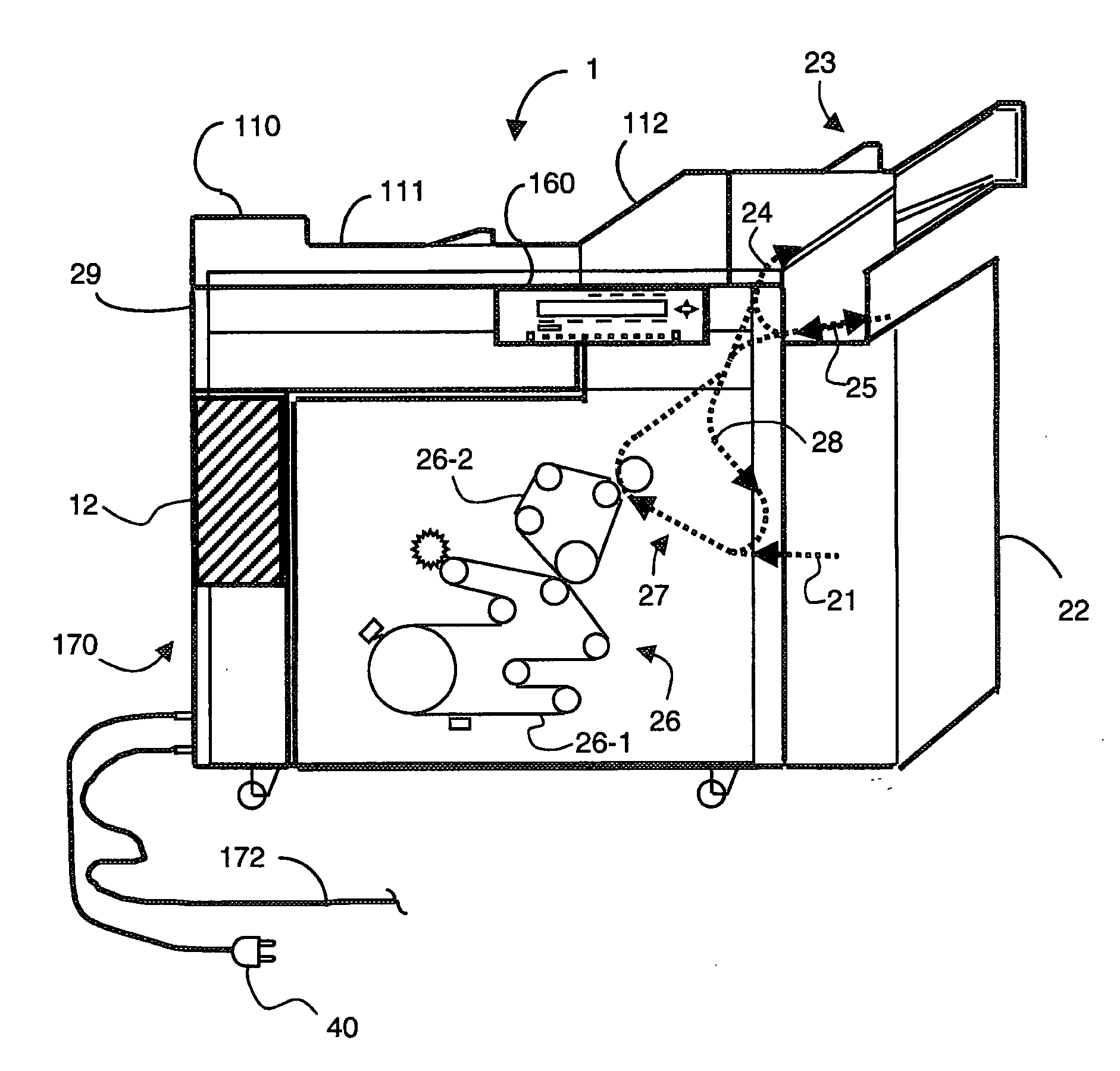
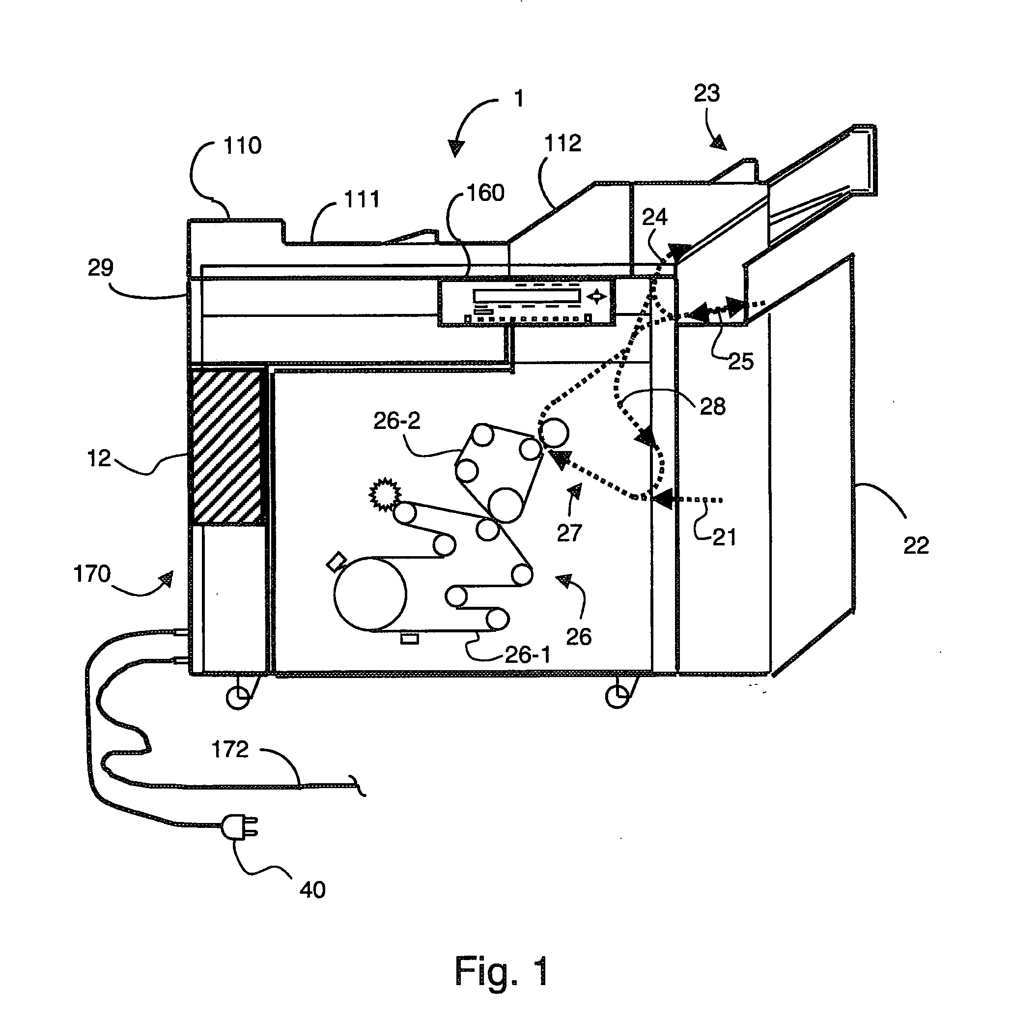
[0031]FIG. 1 shows a digital image reproduction device 1, on which the different parts are separately shown in diagram form. The documents to be processed are usually paper sheets, but may also include any other type of sheets for carrying information, e.g. overhead sheets, etc.

[0032]The device has an input unit 22 for providing sheets, which may have several trays containing sheets to be processed, and an output unit 23 for receiving processed documents.

[0033]The output unit 23 may comprise an output tray, or may be a finisher including sorting, stapling, and further processing of printed sheets.

[0034]The device has a printing system 26 which may include an electro-photographic processing section known per se, in which a photoconductive medium 26-1 is charged, exposed via an LED array in accordance with digital image data...


PUM


Abstract

An image reproduction device includes a print processing system and a print sheet conveying system that conveys sheets with a continuously variable and dynamically adjustable processing speed. The device lowers the processing speed when the mains connection cannot deliver sufficient power to run at a nominal processing speed and is provided with a current monitor unit for monitoring total electrical current drawn by the device from the mains connection and a control unit connected to the current monitor unit and arranged for dynamically adjusting the processing speed to a lower value when the total electrical current is above a preset maximum value. The control unit regulates the lower processing speed value to make sure that the total electrical current drawn by the device from the mains connection is kept substantially equal to the preset maximum current value until the mains power is again sufficient for running at nominal processing speed.

Description

CROSS-REFERENCE TO RELATED APPLICATIONS[0001]This nonprovisional application claims priority under 35 U.S.C. § 119(a) on Patent Application Nos. 06112924.3 and 06118244.0, filed in the European Patent Office on Apr. 21, 2006 and Aug. 1, 2006, respectively. The entirety of each of the above-identified applications is incorporated herein by reference.BACKGROUND OF THE INVENTION[0002]1. Field of the Invention:[0003]The invention relates to an image reproduction device for document processing. More particularly, the invention relates to a device having a processing system for applying visible marks on image support material, including a heat fusing system and a conveying system for conveying the image support material from an input section to the processing system and from the processing system to an output section. The device takes maximal advantage of the energy available from a mains supply, while limiting power consumption to a safe value.[0004]The invention further relates to a met...

Claims


Application Information

Patent Timeline
Patent Type & Authority Applications(United States)
IPC IPC(8): G03G15/00
CPCB41J29/393G03G15/5004G03G15/6529G03G2215/00556G03G2215/00746H04N1/00567H04N1/00652H04N1/00885H04N1/00899H04N1/00904H04N2201/0094G03G15/00
Inventor GRONINGER, MARK A.WAARSING, BEREND J.W.FABEL, RONALD
Owner OCE TECH
Why Eureka
Try Eureka