Magnetron device with mode converter and related methods

a technology of mdo and mode converter, applied in the field of relativistic magnetrons, can solve the problems of low efficiency, difficult for some applications, and complicated radiation pattern of mdo

Active Publication Date: 2009-03-05
STC UNM
View PDF12 Cites 19 Cited by
  • Summary
  • Abstract
  • Description
  • Claims
  • Application Information

AI Technical Summary

Benefits of technology

[0009]The present invention is an improved relativistic magnetron with axial extraction of electromagnetic energy, or magnetron with diffraction output (MDO), that forms simple radiation patterns.
[0011]As shown in FIG. 1, the MDO is based on a conventional magnetron resonant system and includes a cathode 15 and resonant system 20. Resonant system 20 includes cavities that extend in the axial direction and are flush with a conical horn antenna 25 up to a radius that exceeds the radius corresponding to the cutoff frequency of the radiated wave in a regular cylindrical waveguide. FIG. 1 shows some examples of such diffraction output. The symmetrical design of the MDO with axial extraction allows the use of a truly compact magnetic field-producing system in the form of a single short solenoid 30 whose diameter is determined by the outer diameter of the resonant system 20. The coaxial line for magnetron feeding is shown by 35.
[0018]Further increasing the radiated power of magnetrons requires increasing the number of cavities N, which in turn increases the probability of hopping from the operating mode to a neighboring one.
[0020]The diffraction output of the magnetron does not remove the degeneracy because all of the cavities are identically loaded. Therefore, any mode can be selected in the MDO as the operating mode, and possible mode hopping is not dangerous.
[0022]The present invention provides a relativistic magnetron with axial extraction that has the ability to form simple radiation patterns including a narrow wave beam close to a Gaussian radiation pattern. The mode converter is integrated directly within the diffraction output of radiation to effectively convert the operating π-mode into a radiated mode of simpler radiation patterns.
[0024]Another object of the present invention is to provide an improved magnetron device wherein mode conversions are achieved without increasing the dimensions of the diffraction output of radiation, such as the conical horn antenna.

Problems solved by technology

A major problem with the two-pole magnetron was low efficiency.
However, the radiation pattern of a MDO is more complicated than that of the conventional magnetron that can make it difficult for some applications.

Method used


Image

  • Magnetron device with mode converter and related methods
  • Magnetron device with mode converter and related methods
  • Magnetron device with mode converter and related methods

Examples


Embodiment Construction

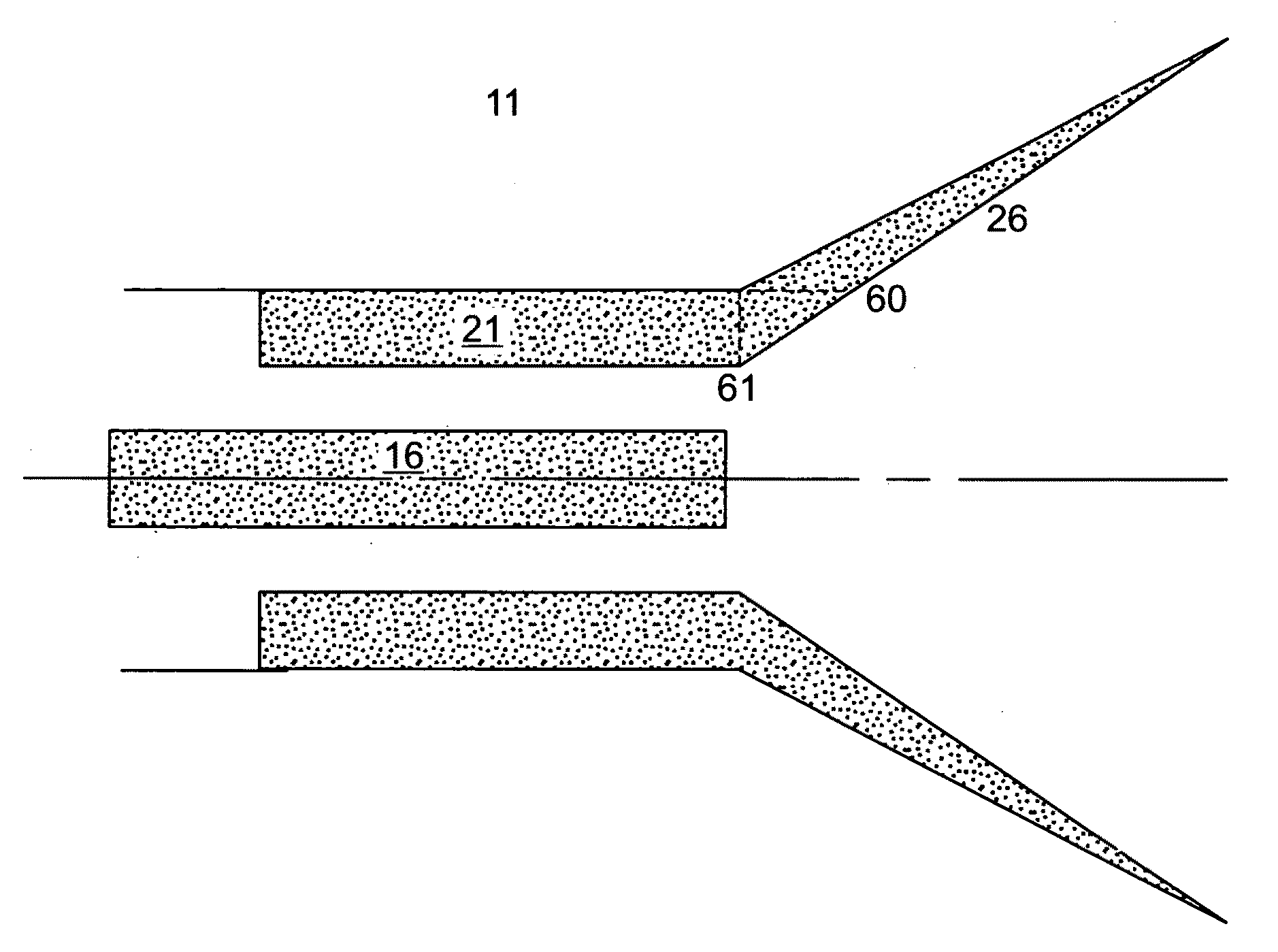
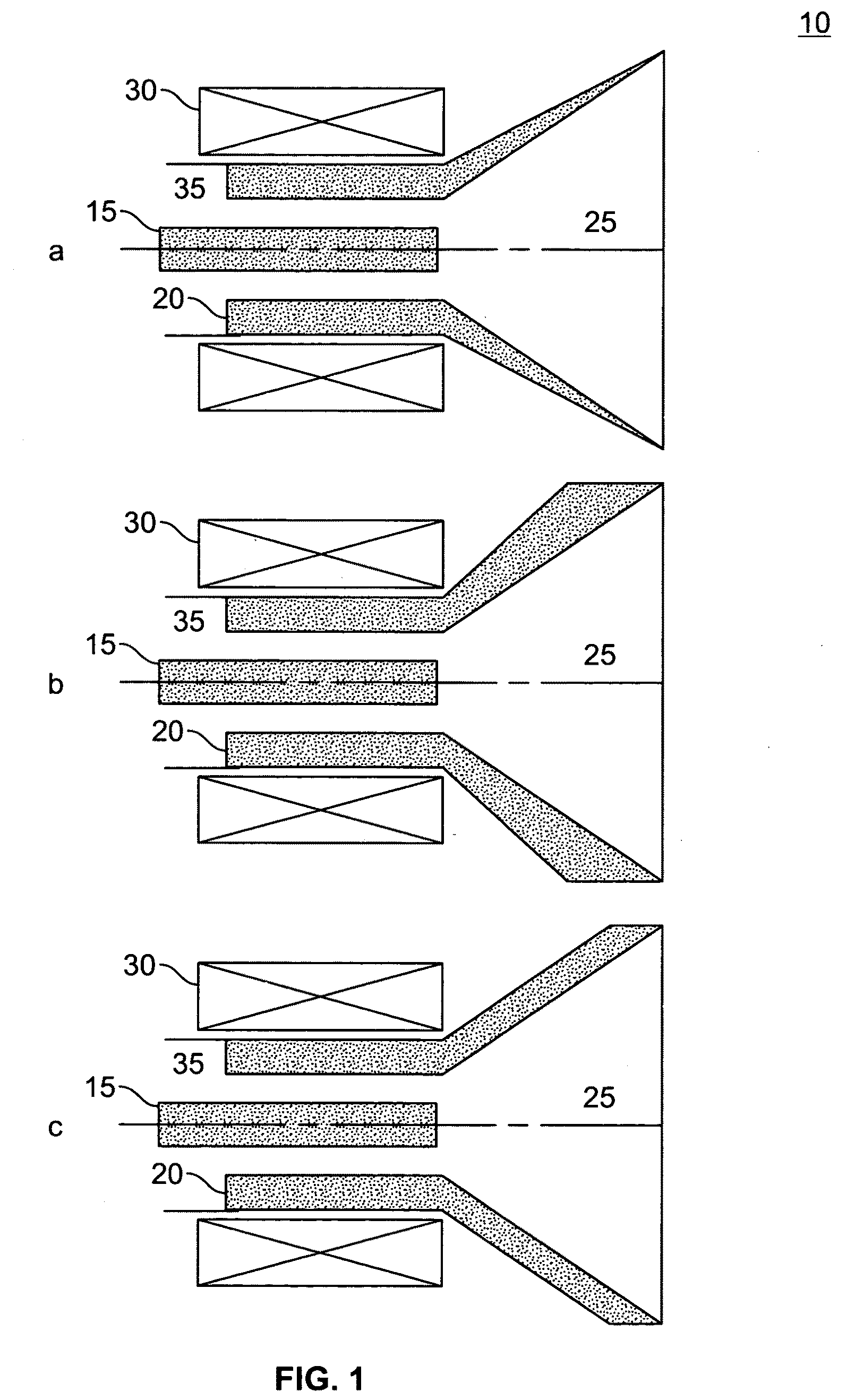
[0052]The present invention provides a relativistic magnetron with axial extraction (see FIG. 1), or magnetron with diffraction output (MDO), that has the ability to form simple radiation patterns including a narrow wave beam close to a Gaussian radiation pattern. The mode converter is integrated directly within the diffraction output of radiation to effectively convert the operating π-mode into a radiated mode of simpler radiation patterns. The efficiency of mode conversion of the operating π-mode into a radiated mode is discussed herein using computer simulations of a 6-cavity magnetron. More specifically, only those cavities of the anode are extended onto an antenna that corresponds to the symmetry of the radiated modes.

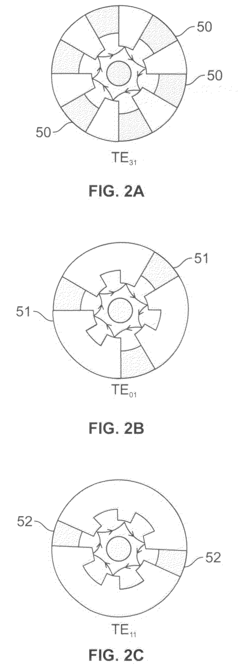
[0053]To illustrate the concept of a mode converter within the MDO, the 6 cavities N=6 of the magnetron are joined with a conical horn antenna. FIG. 4 illustrates a schematic drawing of the conical horn antenna. In the converter, the symmetry of the electric field...


PUM


Abstract

The present invention provides a relativistic magnetron with axial extraction, or magnetron with diffraction output (MDO), with a mode converter placed directly within the diffraction output of radiation to effectively convert the operating π-mode into a radiated mode of simpler radiation patterns.

Description

[0001]This application claims the benefit of U.S. Provisional Application No. 60 / 931,719 filed May 25, 2007.FEDERALLY SPONSORED RESEARCH[0002]The present invention was made with government support under Grant No. N00014-06-1-0476 awarded by the Office of Naval Research. As a result, the Government may have certain rights in this invention.FIELD OF THE INVENTION[0003]The present invention relates to magnetrons, and more specifically to a relativistic magnetron with axial extraction of electromagnetic energy, otherwise known as a magnetron with diffraction output (MDO).BACKGROUND OF THE INVENTION[0004]Magnetrons are compact narrowband high power microwave sources primarily used to generate power at microwave frequencies. Magnetrons are used in applications, for example, radar systems, microwave oven devices, plasma screen apparatuses, plasma lighting, manufacturing such as medical device manufacturing, and linear accelerator applications to name a few.[0005]One of the first magnetrons...

Claims


Application Information

Patent Timeline
Patent Type & Authority Applications(United States)
IPC IPC(8): H01J23/36
CPCH01J23/18H01J25/587H01J23/36
Inventor FUKS, MIKHAIL I.SCHAMILOGLU, EDL
Owner STC UNM
Why Eureka
Try Eureka