Autofocus control circuit, autofocus control method and image pickup apparatus

a control circuit and control method technology, applied in the field of image pickup apparatus, can solve the problems of strong risk of causing misfocusing, particularly prominent risk of misfocusing, and the inability to perform autofocusing, and achieve the effect of increasing computational complexity and reducing the area ratio of background images

Inactive Publication Date: 2009-04-16
RENESAS ELECTRONICS CORP
View PDF3 Cites 15 Cited by
  • Summary
  • Abstract
  • Description
  • Claims
  • Application Information

AI Technical Summary

Benefits of technology

[0024]To address this problem, the autofocus control circuit, the autofocus control method and the image pickup apparatus according to the respective aspects of the present invention described above should preferably set the autofocus target region to a region obtained by reducing the face region in accordance with the area ratio. This makes it possible to set a ce...

Problems solved by technology

However, the camera disclosed in Patent Document 3 neither performs face detection by performing image processing on a captured image nor performs autofocusing on a detected face region.
Determining an autofocus target region so as to include a periphery portion of a face region and a background image around the face region as described above, the technique disclosed in Patent Document 2 has a problem of having a strong risk of causing misfocusing, a phenomenon that, if background occupies a large percentage of the autofocus target region, the background will come into focus while a human face is out of focus.
This misfocusing risk is particularly prominent when a human ...

Method used


Image

  • Autofocus control circuit, autofocus control method and image pickup apparatus
  • Autofocus control circuit, autofocus control method and image pickup apparatus
  • Autofocus control circuit, autofocus control method and image pickup apparatus

Examples


first embodiment

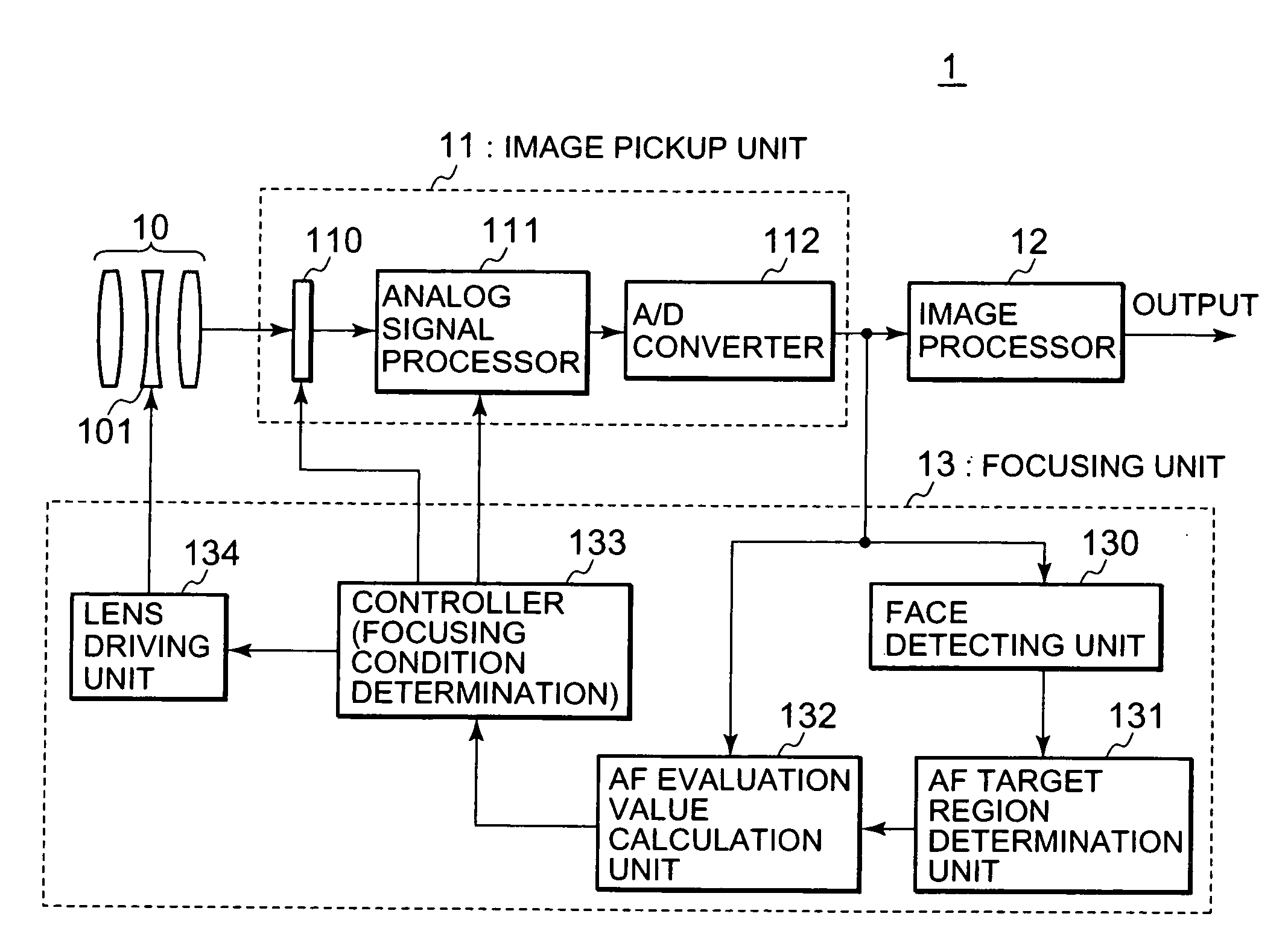
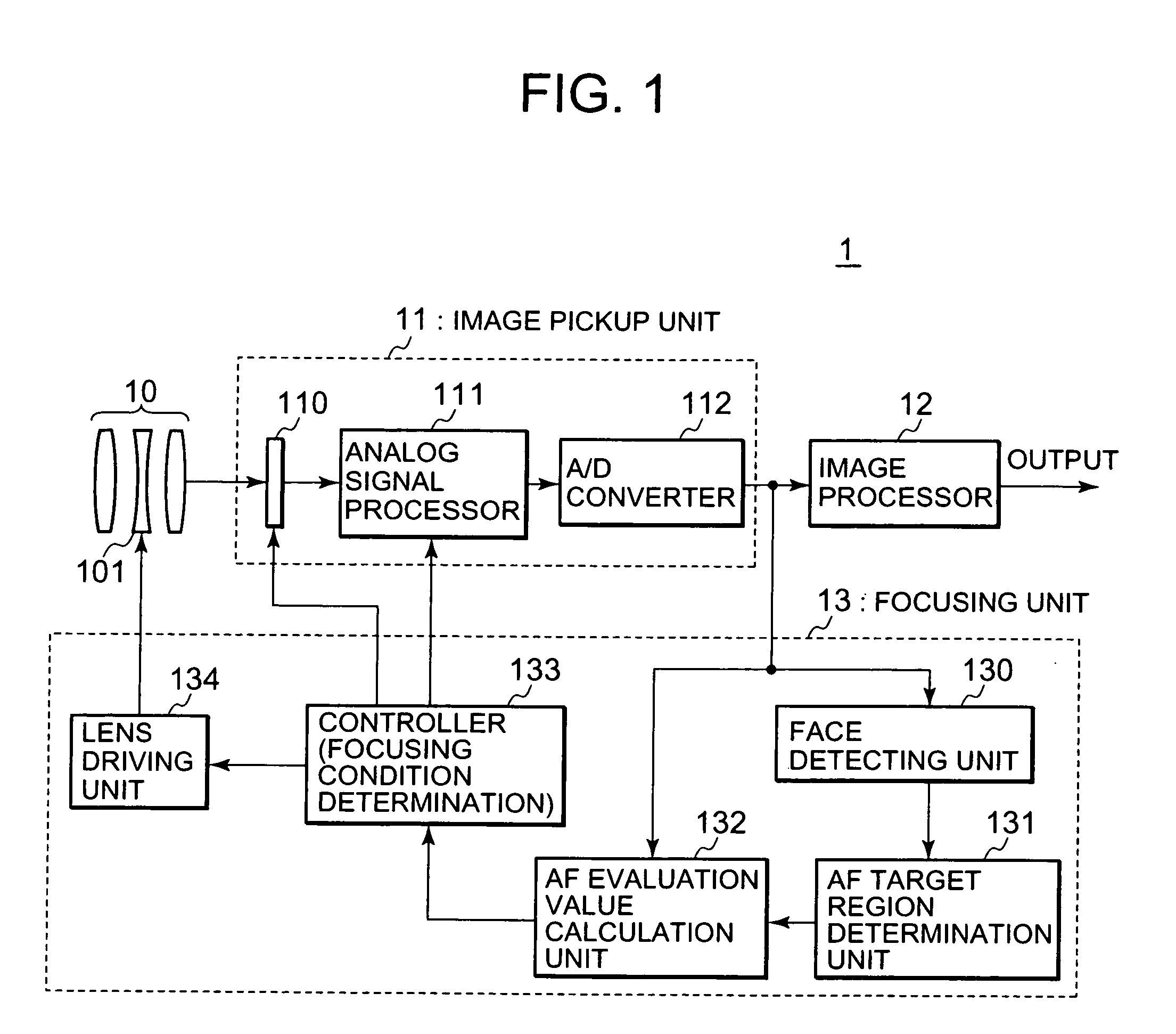
[0033]FIG. 1 is a block diagram showing a main configuration of an image pickup apparatus 1 according to a first embodiment. Hereinbelow, constituents included in FIG. 1 are each described. In FIG. 1, a shooting optical system 10 is a set of optical lenses used for forming a subject image on an imaging surface of an image pickup device 110 to be described later. The shooting optical system 10 includes a focusing lens 101. The focusing lens 101 is driven by driving force of a lens driving unit 134 to be described later, and thus is movable in a direction of the optical axis connecting the shooting optical system 10 and the image pickup device 110.

[0034]An image pickup unit 11 includes the image pickup device 110, an analog signal processor 111 and an A / D converter 112. The image pickup device 110 is a sensor which photoelectrically converts optical signals incident thereon through the shooting optical system 10 to output the resultant signals as analog image signals. The image pickup...

second embodiment

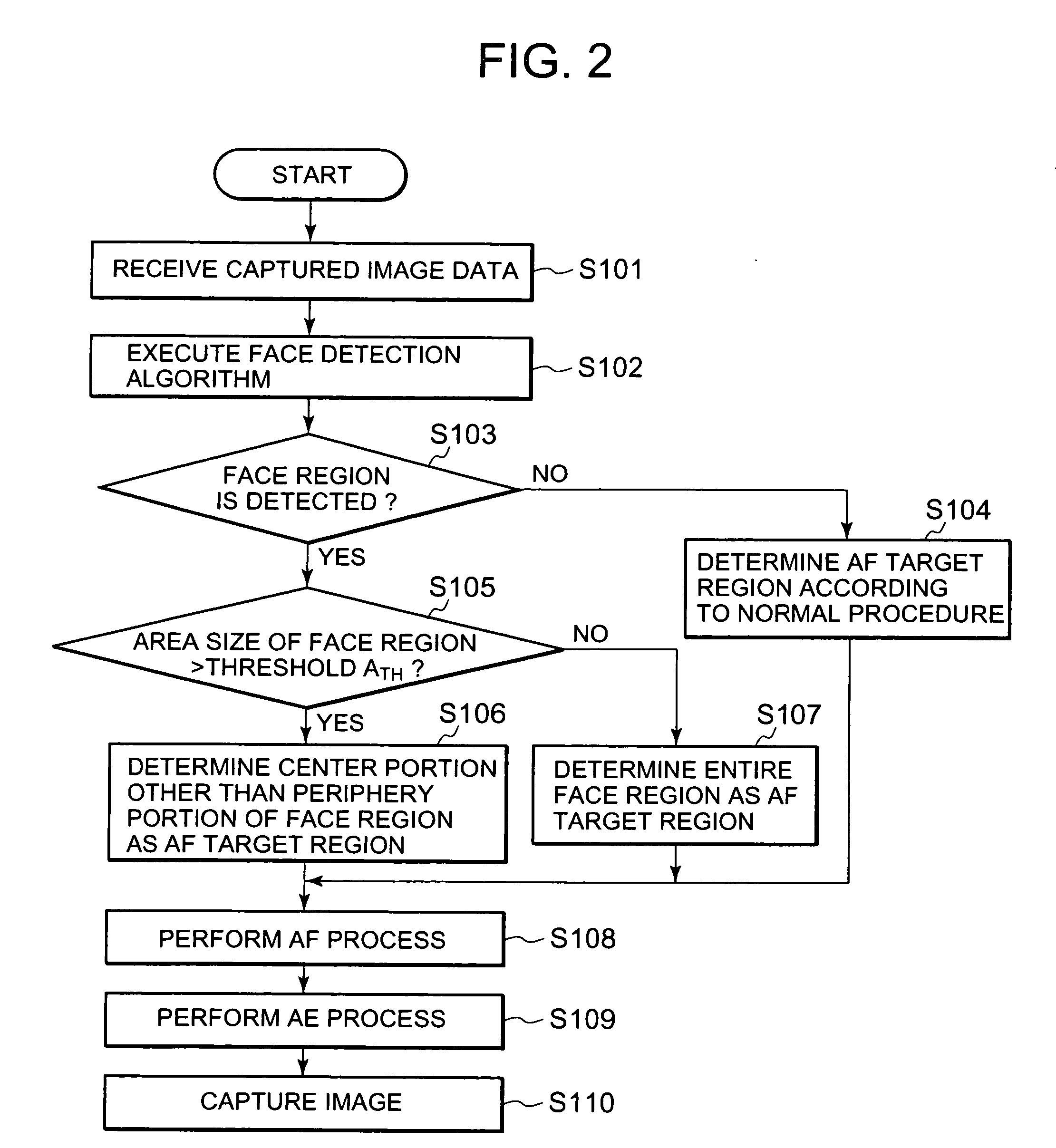
[0059]In the above first embodiment, description will be given of the configuration in which, depending on whether or not the area size of the face region exceeds a threshold ATH, the AF target region is set to either a center portion other than a periphery portion of the face region or the entire face region. However the first embodiment is only a specific example of an image pickup apparatus capable of changing the area ratio of an AF target region to a face region in accordance with the size of the face region. An image pickup apparatus according to a second embodiment is another example of an image pickup apparatus capable of changing the area ratio of an AF target region to a face region in accordance with the size of the face region.

[0060]A configuration of the image pickup apparatus according to this embodiment may be set similar to that of the image pickup apparatus 1 shown in FIGS. 1 and 5. Accordingly, the configuration diagram of the image pickup apparatus according to th...


PUM


Abstract

The invention aims to reduce, in performing autofocusing on an autofocus target region determined within a face region obtained by face detection, the risk of misfocusing attributable to a background image included in the autofocus target region. To this end, a face detecting unit firstly performs face detection to determine a face region including a human face image. Then, an AF target region determination unit determines an AF target region within the face region. In this event, the AF target region determination unit can change the area ratio of the AF target region to the face region. Thereafter, based on contrast of a region, corresponding to the AF target region determined by the AF target region determination unit, of captured image data, an AF evaluation value calculation unit, a controller and a lens driving unit adjust a location where a subject image is formed by a shooting optical system.

Description

BACKGROUND OF THE INVENTION[0001]1. Field of the Invention[0002]The present invention relates to an image pickup apparatus, especially to an autofocus technique of automatically determining a focusing condition of a subject image in an image pickup apparatus.[0003]2. Description of the Related Art[0004]Heretofore, image pickup apparatuses each including an image pickup device such as a charge coupled device (CCD) sensor or a complementary metal oxide semiconductor (CMOS) sensor has been put to practical use. Examples of such image pickup apparatuses are a digital still camera and a digital video camera. In addition, as an autofocus system applied to these electronic image pickup apparatuses, a contrast detection system based on an image captured by an image pickup device is known.[0005]The contrast detection system is based on the principle that when a subject image formed onto an imaging surface of an image pickup device by a shooting optical system is in an in-focus condition, the...

Claims


Application Information

Patent Timeline
IPC IPC(8): G02B7/04
CPCG02B7/36G03B13/36H04N23/67
Inventor OTSUKI, TAKESHI
Owner RENESAS ELECTRONICS CORP
Why Eureka
Try Eureka