Direct Injection Fuel System with Reservoir

a fuel system and reservoir technology, applied in the direction of machines/engines, electric control, engine starters, etc., can solve the problems of reducing engine power and efficiency, fuel may not sufficiently mix with the air in the cylinder, insufficient mixing, etc., and achieve the effect of improving the fuel pressure ris

Inactive Publication Date: 2009-04-30
FORD GLOBAL TECH LLC
View PDF42 Cites 12 Cited by
  • Summary
  • Abstract
  • Description
  • Claims
  • Application Information

AI Technical Summary

Benefits of technology

[0007]Thus, improved fuel pressure rise

Problems solved by technology

One potential issue with GDI is that under lower injection pressures the fuel may not sufficiently mix with the air in the cylinder.
Insufficient mixing may decrease engine power and efficiency, and increase emissions, at least under some conditions.
For example, during cold engine starts, and before the catalytic converter is activated, insufficient mixing may exacerbate cold start emissions.
However, fuel delivery systems may also experience compressible gas (air, fuel vapors, etc.) in the fuel line.
In particular, a vacuum in the fuel rail may form when the fuel cools during engine-off conditions.
The vacuum may cause air to leak through the fuel injectors into the fuel rail.
The leakage may create a mixture of air vapor and liquid fuel in the fuel line, which in turn may degrade the fue

Method used


Image

  • Direct Injection Fuel System with Reservoir
  • Direct Injection Fuel System with Reservoir
  • Direct Injection Fuel System with Reservoir

Examples


Embodiment Construction

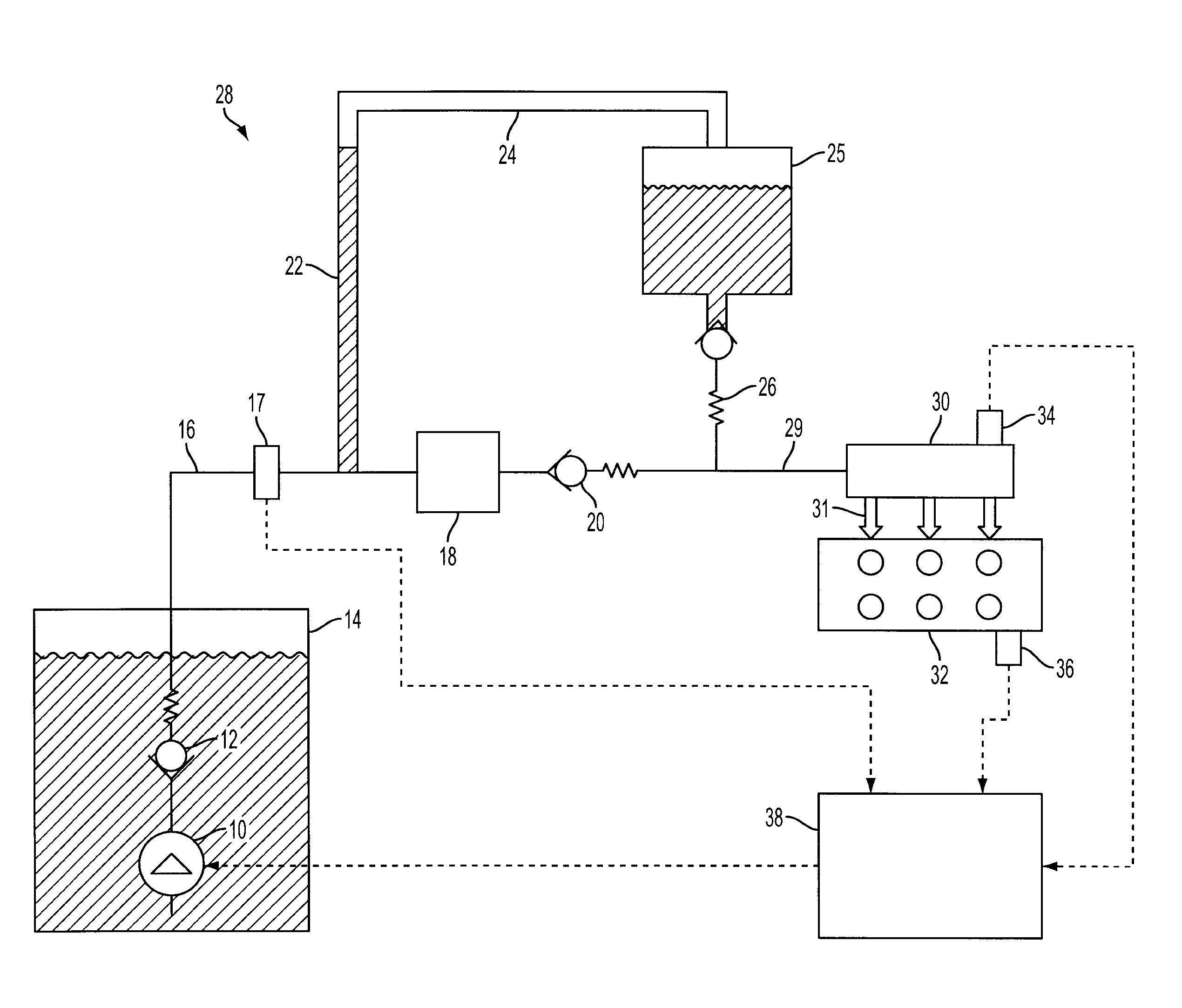
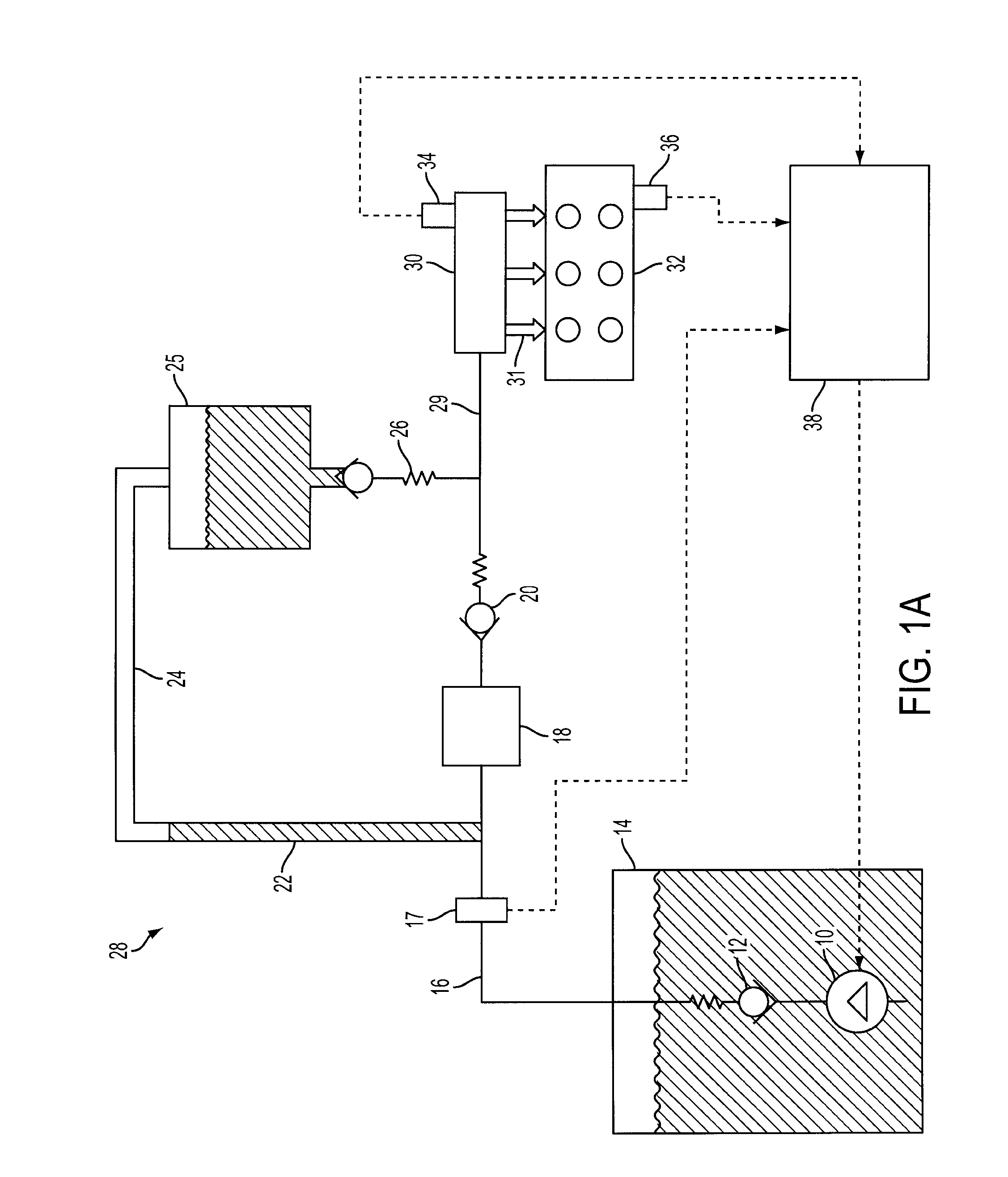
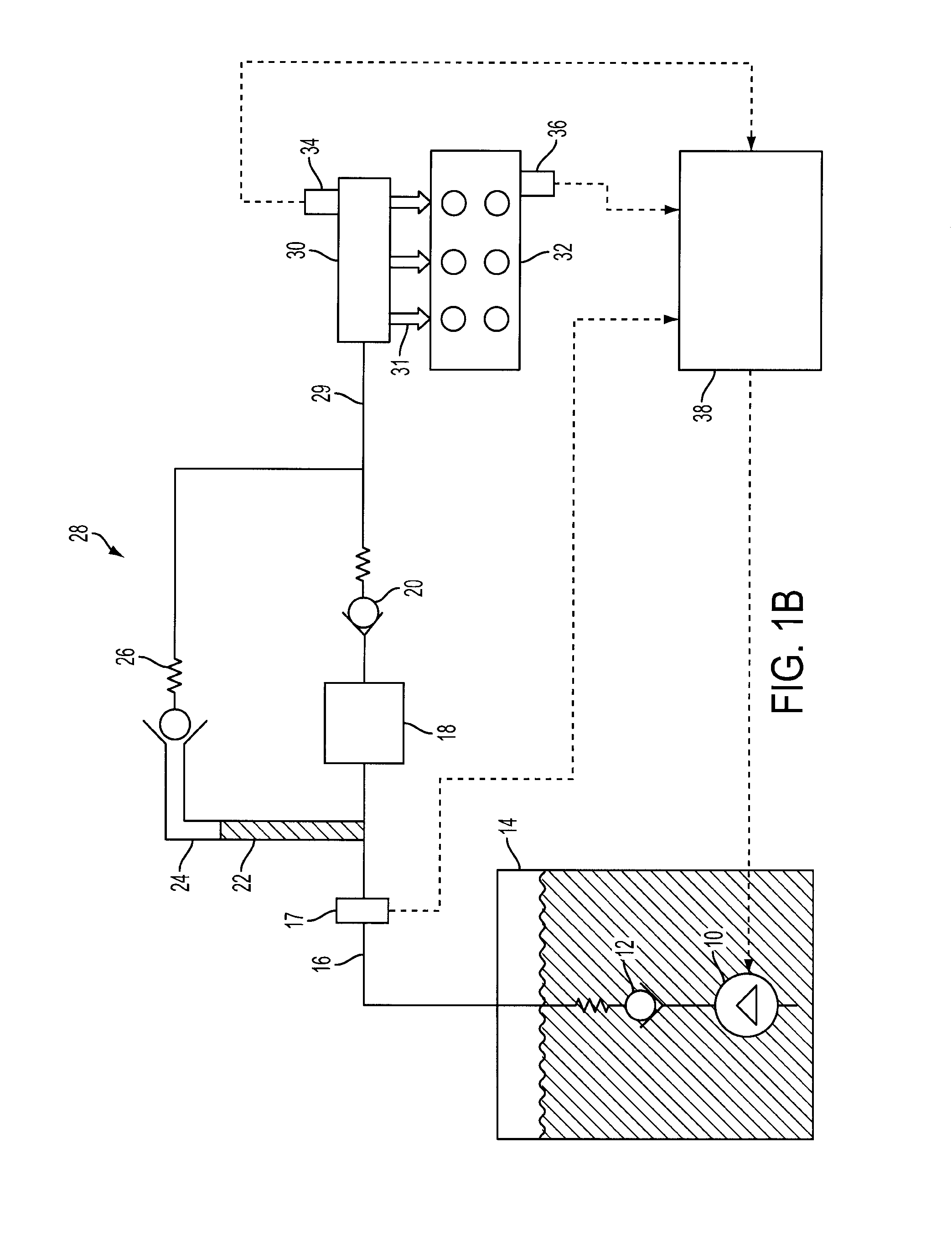
[0012]FIG. 1 shows a schematic depiction of a fuel delivery system for an internal combustion engine. Pump 10 may include various types of pumps, such as an electric pump operated at a fixed voltage where an in-tank or near tank regulator sets generated pressure, or an electronically controlled pump which runs at two or more voltage levels based on operating conditions. FIG. 1 shows the configuration for the latter pump. For example, the pump may operate at full power (e.g., 100%) or a reduced power level (e.g., 75%) based on operating conditions. In alternate embodiments the lift pump may run in a variable duty cycle. Controller 38 electronically controls actuation of lift pump 10. Pump 10 is fluidly coupled to check valve 12. In this embodiment check valve 12 is a ball and spring check valve that unseats at a specified pressure differential. In alternate embodiments there may be a series of check valve fluidly coupled to decrease the amount of fuel that leaks through the check val...


PUM


Abstract

A method of operating a fuel delivery system for an internal combustion engine is described. The system may include a plurality of direct cylinder injectors, a fuel rail upstream of the injectors, a first pump, and a second pump coupled downstream of the first pump and to the fuel rail. The method may include, after or during engine shutdown, and during a fuel system cool down, activating the first pump; and varying the activation of the first pump responsive to temperature to maintain a higher pressure for high temperatures. Alternatively, in some examples, the system may include a reservoir in a bypass around the second pump, the bypass having a valve downstream of the fuel reservoir, where the valve is positioned vertically above the second pump and the fuel reservoir is positioned vertically above the valve. The fuel reservoir may be sized to hold a sufficient amount of fuel in the bypass to allow fuel to migrate from the bypass to the fuel rail during engine cool down.

Description

BACKGROUND AND SUMMARY[0001]Internal combustion engines may utilize Gasoline Direct Injection (GDI) to increase the power efficiency and range over which the fuel can be delivered to the cylinder. One potential issue with GDI is that under lower injection pressures the fuel may not sufficiently mix with the air in the cylinder. Insufficient mixing may decrease engine power and efficiency, and increase emissions, at least under some conditions. For example, during cold engine starts, and before the catalytic converter is activated, insufficient mixing may exacerbate cold start emissions. Thus, increased injection pressure during a start may be used.[0002]However, fuel delivery systems may also experience compressible gas (air, fuel vapors, etc.) in the fuel line. In particular, a vacuum in the fuel rail may form when the fuel cools during engine-off conditions. The vacuum may cause air to leak through the fuel injectors into the fuel rail. The leakage may create a mixture of air vapo...

Claims


Application Information

Patent Timeline
IPC IPC(8): F02M69/46F02N99/00
CPCF02B2075/125F02D33/006F02D41/062F02D41/3082F02D41/3836F02D41/3863Y02T10/123F02D2041/225F02D2250/02F02M37/0064F02M37/10F02M37/20F02M63/023F02D2041/224Y02T10/12
Inventor ULREY, JOSEPH NORMANSTORHOK, ERIC MATTHEWPURSIFULL, ROSS DYKSTRAGONZALES, JR., FRANK
Owner FORD GLOBAL TECH LLC
Why Eureka
Try Eureka