LED drive circuit

a technology of led drive circuit and drive circuit, which is applied in the direction of electric variable regulation, process and machine control, instruments, etc., can solve the problems of high component and development cost, source of electromagnetic interference,

Active Publication Date: 2009-07-09
TEXAS INSTR INC
View PDF3 Cites 66 Cited by
  • Summary
  • Abstract
  • Description
  • Claims
  • Application Information

AI Technical Summary

Benefits of technology

[0005]The present invention was devised in light of the aforementioned problem of conventional technology, and its general objective is to present a low-cost LED drive circuit that is equipped with an effective EMI-prevention function while allowing LED pulse-lighting characteristics to be controlled as desired.

Problems solved by technology

There is a problem that a high-frequency LED drive current that flows when the aforementioned PWM-based switching operation is carried out to turn on / off the many LEDs at the same time becomes a source of electromagnetic interference (EMI: Electromagnetic Interference).
However, said conventional measure is disadvantageous in that it incurs high component and development costs.

Method used


Image

  • LED drive circuit
  • LED drive circuit
  • LED drive circuit

Examples


Embodiment Construction

[0037]According to the LED drive circuit of the present invention, LED pulse-lighting characteristics can be controlled as desired due to the aforementioned configuration and function, and EMI can be typically prevented effectively at a low cost. An embodiment of the present invention will be explained below with reference to attached figures.

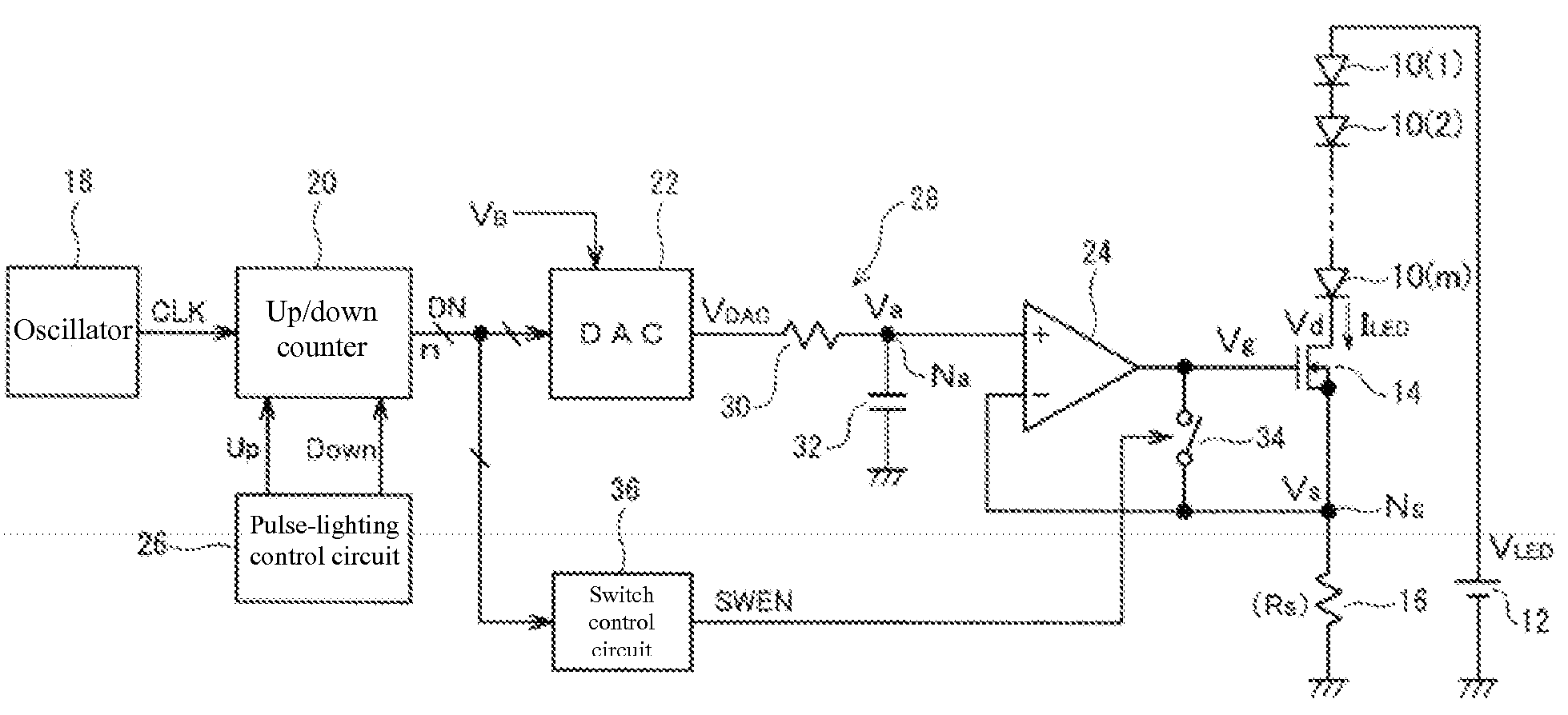
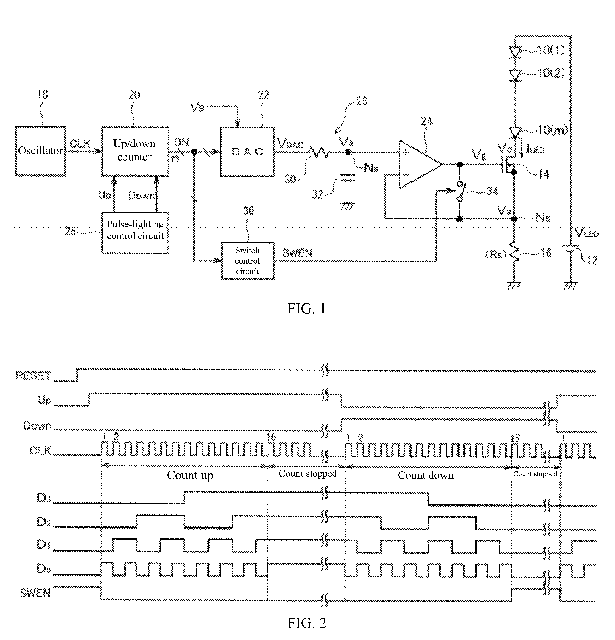
[0038]The configuration of an LED drive circuit of an embodiment of the present invention is shown in FIG. 1. This LED drive circuit is used to drive many LEDs that are arranged in a matrix for LED backlighting, for example, by means of a pulse-lighting method. The illustrated circuit configuration is used to control the lighting of m units of LEDs 10(1), 10(2), . . . , and 10(m), that are provided in a row, in a block. Said m units of LEDs 10(1)-10(m) are connected to DC power supply 12 that outputs specific drive voltage VLED, in series in the forward direction, and NMOS transistor 14 and resistor 16 are connected in series in said order betw...


PUM


Abstract

A LED drive circuit equipped with oscillator 18, up/down counter 20, and DAC 22 in order to drive multiple LEDs 10(1)-10(m) in a block. Up/down counter 20 carries out count-up/down operations in sync with clock CLK sent from oscillator 18 during the ramping up/down of pulse-lighting of the LEDs. DAC 22 converts counter count value DN into analog voltage signal VDAC and supplies it to the gate terminal of NMOS transistor 14 via low-pass filter 28 and buffer amplifier 24.

Description

FIELD OF THE INVENTION[0001]The present invention pertains to an LED drive circuit for lighting LEDs. In particular, it pertains to an LED drive circuit for pulse-lighting of LEDs.BACKGROUND OF THE INVENTION[0002]Currently, LEDs (light-emitting diodes) that emit high-intensity light or light in a variety of colors, including white, are developed, mass-produced, and utilized for a wide range of applications, such as illumination.[0003]DC-lighting and pulse-lighting are available as methods for lighting LEDs. For example, pulse-lighting is utilized as an LED-based backlight of a liquid crystal display. In general, in the case of an LED-based backlight, the LEDs are pulse-lighted by means of pulse width modulation (PWM) at a specific frequency (for example, 10 KHz), and the brightness is adjusted by means of the ratio (duty ratio) between on (on) time and off (off) time within each cycle. In this case, during each cycle, an LED drive circuit is used to carry out switching operations su...

Claims


Application Information

Patent Timeline
Patent Type & Authority Applications(United States)
IPC IPC(8): H05B37/02H01L33/00H01L33/12
CPCH05B33/0818Y02B20/346H05B33/0851H05B45/10Y02B20/30
Inventor MURAMATSU, YASUNORI
Owner TEXAS INSTR INC
Why Eureka
Try Eureka