Downhole Debris Catcher and Associated Mill

Active Publication Date: 2009-08-13
BAKER HUGHES INC
View PDF7 Cites 18 Cited by
  • Summary
  • Abstract
  • Description
  • Claims
  • Application Information

AI Technical Summary

Benefits of technology

[0009]A debris catching device for downhole milling features modular debris receptacles that are held in the housing in a manner that facilitates stacking and a generally undulating flow path to facilitate dropping of the debris into the receptacles as the remaining fluid travels up the tool for ultimate screening before the fluid exits the tool to flow up to the surface or in a reve

Problems solved by technology

Another issue was that tube 32 was prefabricated to a predetermined length which limited the volume of the annular space 20.
However, in conjunction with the debris catcher shown in FIG. 1 there

Method used


Image

  • Downhole Debris Catcher and Associated Mill
  • Downhole Debris Catcher and Associated Mill
  • Downhole Debris Catcher and Associated Mill

Examples


Embodiment Construction

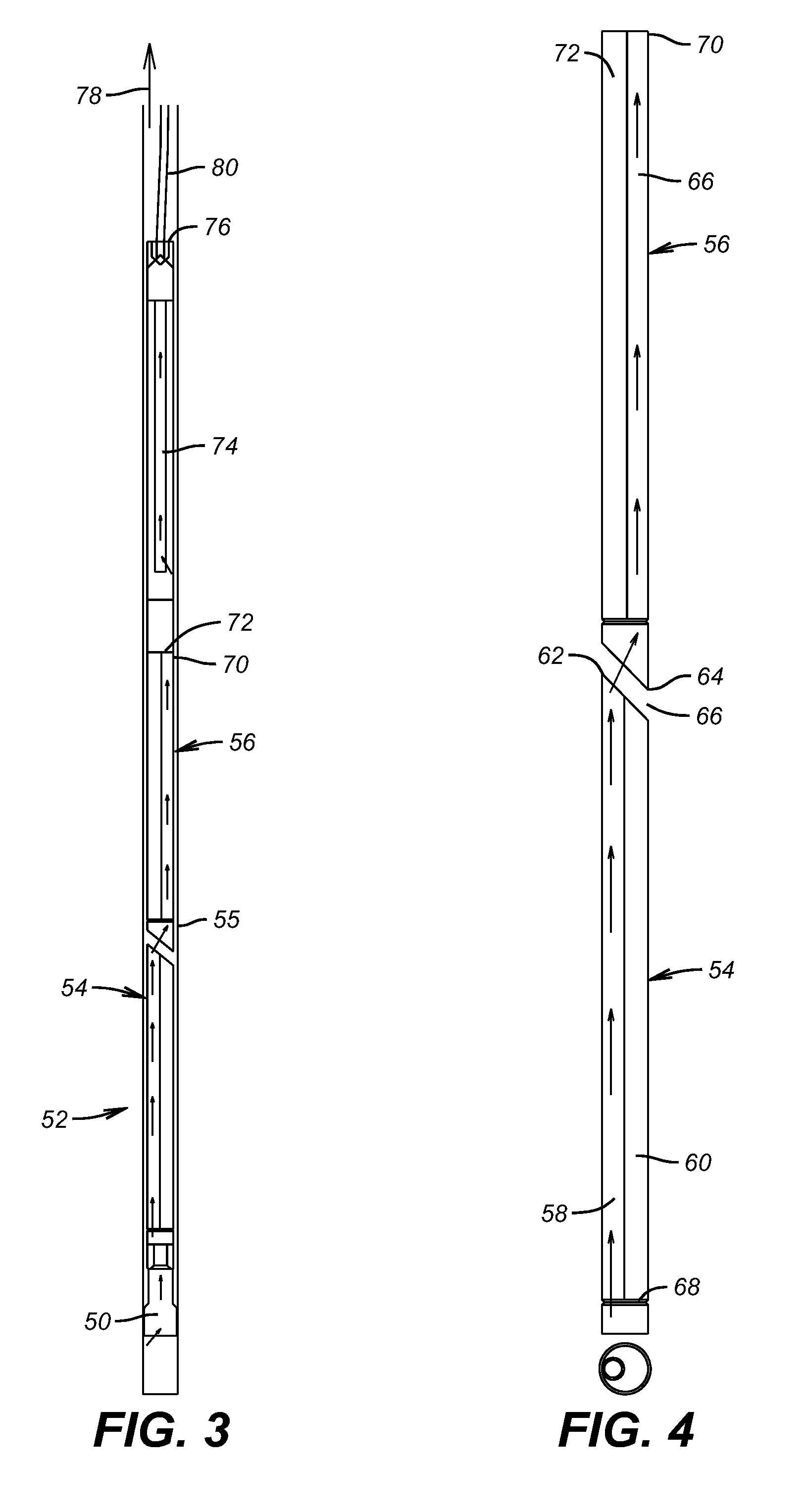
[0018]FIG. 5 shows a mill 50 with one embodiment of the debris catching tool 52 mounted above it. In this embodiment there are modules 54 and 56 shown in housing 55 although additional modules can be used. The modules 54 and 56 are shown in larger scale in FIG. 4 and without the housing 55 so that the flow pattern can be more easily seen. Debris laden fluid from the mill 50 enters passage 58 in module 54. Sitting beside passage 58 is passage 60 with both passages open at the upper end 62 of module 54. Upper end 62 is beveled and lower end 64 of module 56 is also beveled in a conforming way leaving a gap 66 between ends 62 and 64. Passage 58 continues up the tool into passage 66 of module 56. Passage 60 in module 54 has a closed bottom 68. When debris laden fluid exits passage 58 at the top 62 the velocity slows and the fluid stream has to negotiate a double bend to continue into passage 66. The combination of a slowing velocity and making the double bend to a position over the passa...


PUM


Abstract

A debris catching device for downhole milling features modular debris receptacles that are held in the housing in a manner that facilitates stacking and a generally undulating flow path to facilitate dropping of the debris into the receptacles as the remaining fluid travels up the tool for ultimate screening before the fluid exits the tool to flow up to the surface or in a reverse circulation pattern back to the mill below the debris catcher. The modules can also be aligned with flapper valves at the top of each module to prevent debris in the tool from falling to the mill if circulation is turned off. The mill is configured to have an off-center return path preferably as large as the passage through the mill body to aid circulation and cutting performance.

Description

PRIORITY INFORMATION[0001]This application is a divisional application claiming priority from U.S. patent application Ser. No. 12 / 029,228, filed on Feb. 11, 2008.FIELD OF THE INVENTION[0002]The field of this invention is downhole debris catching tools and more specifically those that reverse circulate into a mill to capture the cuttings as they come up through the tool.BACKGROUND OF THE INVENTION[0003]Milling Operations downhole generate cuttings that a captured in tools associated with a mill frequently referred to in the industry as junk catchers. There are many configurations for such tools. Some have external seals that direct cuttings coming up from a mill around the outside of the tool back into the tool so that the circulating fluid can exit while the debris is captured in the tool body. Examples of this design are U.S. Pat. Nos. 6,176,311 and 6,607,031. Another design involves establishing a reverse circulation with jets that discharge outside a tool body toward a mill below...

Claims


Application Information

Patent Timeline
IPC IPC(8): E21B29/00
CPCE21B29/002E21B27/005
Inventor DAVIS, JOHN P.TRAHAN, JAMES S.CONNELL, PAUL L.
Owner BAKER HUGHES INC
Why Eureka
Try Eureka