Chair frame for a stackable chair

Active Publication Date: 2005-03-01
DANIEL PAUL CHAIRS
View PDF12 Cites 13 Cited by
  • Summary
  • Abstract
  • Description
  • Claims
  • Application Information

AI Technical Summary

Benefits of technology

The present invention provides a chair frame for a stackable chair. The chair frame comprises a seat support portion for support a chair seat, and a pair of leg assemblies oppositely disposed on either side of the seat support portion. Each leg assembly includes a front leg and a rear leg, and an upper support member. Each upper support member has an upper surface, at least a portion of which defines a curvilinear surface portion. In the preferred illustrated embodiments of the invention this curvilinear surface portion defines either a convex configuration, or a truncated convex configuration. Each leg assembly also includes a stacking bar extending between the front leg and the rear leg, the stacking bar being disposed below, and being selectively space from the upper support member. The stacking bar of each leg assembly has a lower surface,

Problems solved by technology

Whereas seat cushions generally will serve to support chairs stacked thereon, the flexibility of the cushion can undermine the stability of the resulting stack of chairs such that relatively few chairs can be safely stacked.
These impressions are aesthetically undesirable, and over time damage can result, requiring the replacement of the cushion or replacement of the chair.
Whereas this design avoids the problem of an irregular surface of the upper chair resting upon the seat cushion of the chair below, undesirable pressure is still exerted on the seat cushion, and the folding back portion of the chair makes the chair expensive and complicated to manuf

Method used


Image

  • Chair frame for a stackable chair
  • Chair frame for a stackable chair
  • Chair frame for a stackable chair

Examples


Embodiment Construction

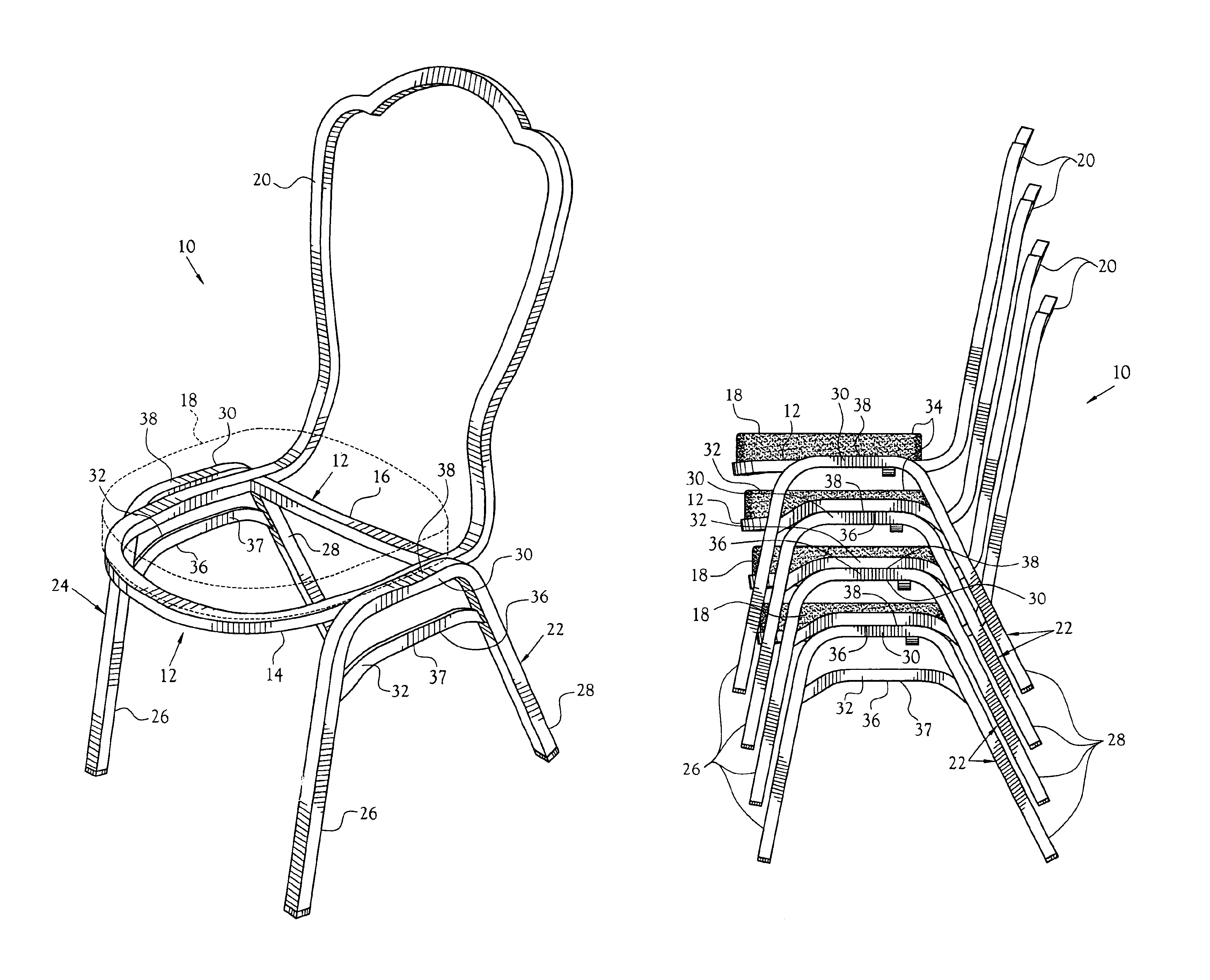
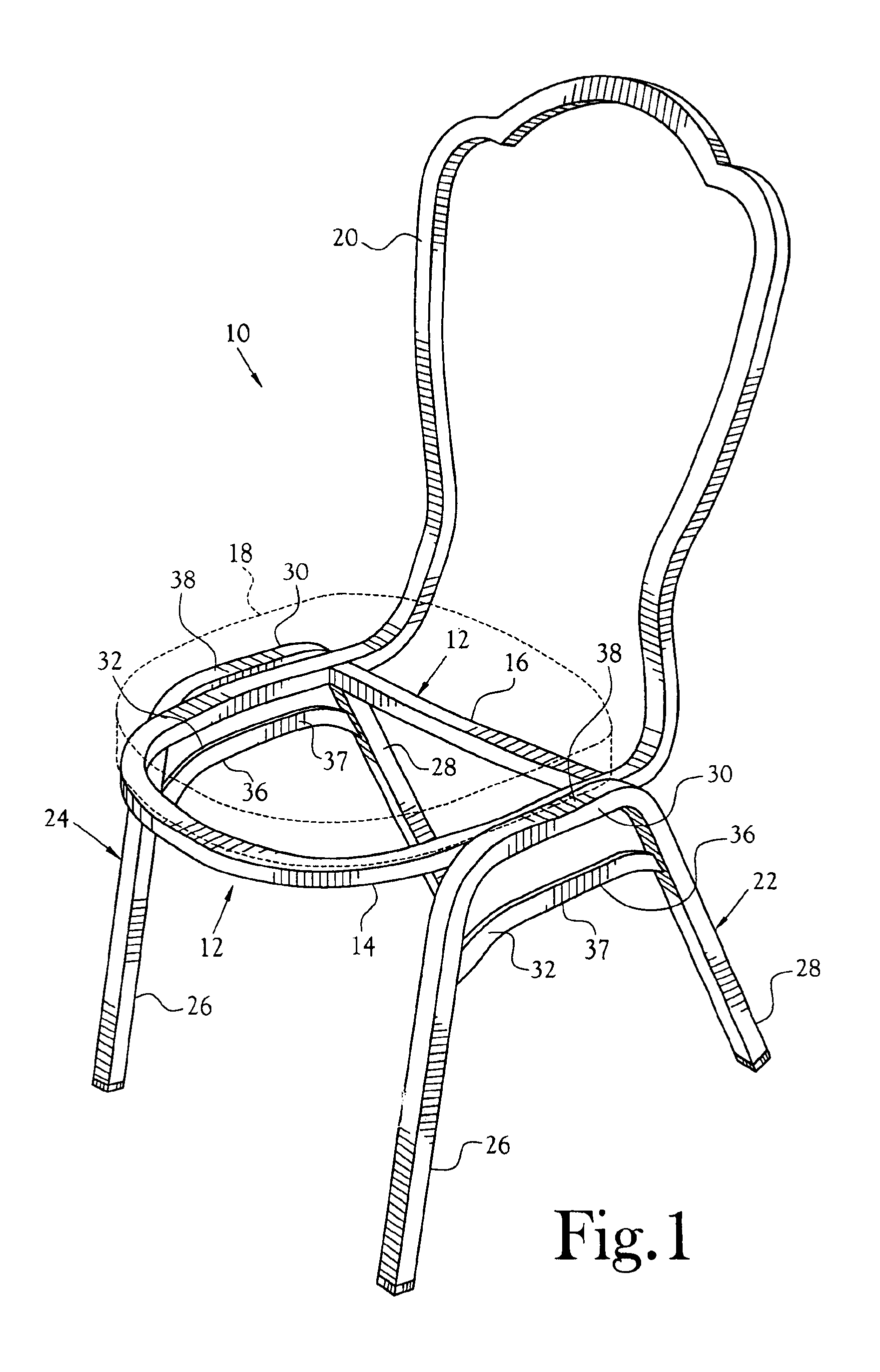
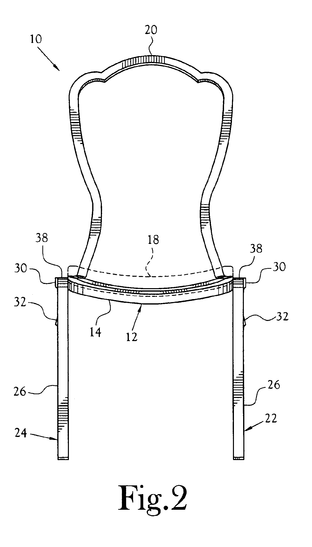
A chair frame for a stackable chair incorporating various features of the present invention is illustrated generally at 10 in FIGS. 1-7. As is illustrated in FIG. 7, and as will be discussed in detail below, the chairs 10 are designed such that they may be stacked, one upon another, to facilitate the storage of a plurality of chairs. For purposes of the discussion herein, the term “chair” is intended to include chairs, benches and stools, as well as other seating structures having legs of various lengths.

The chair frame 10 includes a seat support portion 12 which in the preferred illustrated embodiment defines a generally U-shaped frame portion 14 and a cross support member 16 which extends across, and is secured at its opposite ends to, the frame portion 14. The seat support portion 12 is used to support the seat portion of a chair utilizing the frame 10, such as the seat portion 18 illustrated in broken lines in the figures. Whereas the seat support portion 12 of the chair frame 1...


PUM


Abstract

A chair frame (10) for a stackable chair. The chair frame (10) includes a seat support portion (12) for support the seat portion (18) of a chair, and includes a pair of leg assemblies (22, 24) oppositely disposed on either side of the seat support portion (12). Each leg assembly (22, 24) includes a front leg (26) and a rear leg (28), and an upper support member (30). Each upper support member (30) has an upper surface (38), at least a portion of which defines a curvilinear surface portion. Each leg assembly (22, 24) also includes a stacking bar (32) extending between the front leg (26) and the rear leg (28), the stacking bar (32) being disposed below, and being selectively space from, the upper support member (30). The stacking bar (32) of each leg assembly (22, 24) has a lower surface (36), at least a portion of which defines a curvilinear surface portion configured to closely engage at least a portion of the curvilinear surface portion of the upper surface (38) of the upper support member (30) of another chair frame (10) to facilitate the stacking of a plurality of chairs utilizing the chair frame (10).

Description

CROSS-REFERENCE TO RELATED APPLICATIONSNot ApplicableSTATEMENT REGARDING FEDERALLY SPONSORED RESEARCH OR DEVELOPMENTNot ApplicableBACKGROUND OF THE INVENTION1. Field of InventionThis invention relates to a chair frame for stackable chairs. More specifically, the present invention is related to a chair frame for a stackable chair which incorporates stacking bars which facilitate the stable stacking of chairs utilizing the frame such that the chairs can be safely stored.2. Description of the Related ArtChairs which can be stacked upon one another to facilitate their storage are known in the art. For example, such chairs are disclosed in U.S. Pat. No. 3,316,016. Typically, however, when chairs such as those disclosed in U.S. Pat. No. 3,316,016 are stacked the lower surface of the seat bottom of one chair is supported on the seat cushion of the chair below it. Whereas seat cushions generally will serve to support chairs stacked thereon, the flexibility of the cushion can undermine the s...

Claims


Application Information

Patent Timeline
IPC IPC(8): A47C3/04A47C3/00
CPCA47C3/04
Inventor BARILE, SR., PETERBARILE, JR., PETER W.
Owner DANIEL PAUL CHAIRS
Why Eureka
Try Eureka