Frame for a table

Active Publication Date: 2012-10-25
HUNTER INDUSTRIES +1
View PDF0 Cites 27 Cited by
  • Summary
  • Abstract
  • Description
  • Claims
  • Application Information

AI Technical Summary

Benefits of technology

[0059]Yet another aspect is a table that may include spacers, inserts or pads, which may facilitate stacking of the tables. For example, when tables are stacked and/or nested for manufacturing, transportation, storage, display and the like, a significant amount of weight or force may be applied to the tables. The weight or force may be particularly significant for the tables disposed towards the lower portion of the stack. In addition, because the features disclosed herein may allow significantly more tables to be stacked (such as stacking twenty-seven (27) or twenty-nine (29) tables on a pallet rather than the traditional stacking of twenty-one (21) tables on a pallet), a considerable amount of weight or force may be applied to the tables. The spacers, inserts or pads may be used to prevent damage to the tables. For instance, a pad may include a clip sized and configured to be attached to a portion of the frame, such as a cross member, support structure or other suitable portion of the frame. The pad may include a generally planar surface sized and configured to contact an upper surface of an adjacent table. The pad may help distribute the weight or force more equally, evenly and over a larger surface area on the adjacent table. Advantageously, because the pad may be attached by a clip, that may allow the pad to be easily and quickly attached and/or removed by the manufacturer, retailer, consumers and the like. In addition, the number of pads may depend upon the number of tables to be stacked. For instance, a larger number of pads may be used if a greater number of tables are to be stacked.
[0060]Still another aspect is a table that may include one or more foot caps attached to the feet of the legs. For example, the table may include legs or a support structure with two elongated members connected by a connecting member. The elongated members may be constructed from tubular pieces of metal with a generally circular, oval, oblong or rectangular cross-sectional configuration. The elongated members may be bent or curved such that the upper portions of the elongated members are spaced closer together than the lower portions of the elongated members. This may help create, for example, a more stable table with increased leg room. The foot caps may include an upper portion securely connected to the ends of the elongated members and a lower portion that contacts a support surface such as the ground or floor. Because the ends of the elongated members may be disposed at an angle, such as about 8°, which may be caused by bending the elongated members into the desired shape or configuration, the foot caps are preferably designed to include a lower surface that is disposed parallel to the floor. In addition, the elongated members and the foot caps may include alignment members. For instance, the elongated members may include a notch, cutout, groove, indentation or the like; and the foot caps may include a corresponding projection, protrusion, protuberance or the like. These alignment members may help ensure the elongated members and foot caps are correctly attached in the desired positions and configurations.
[0061]Still yet anothe

Problems solved by technology

Advantageously, this may decrease the amount of space required to store and/or transport the table.
Further, a l

Method used


Image

  • Frame for a table
  • Frame for a table
  • Frame for a table

Examples


Example

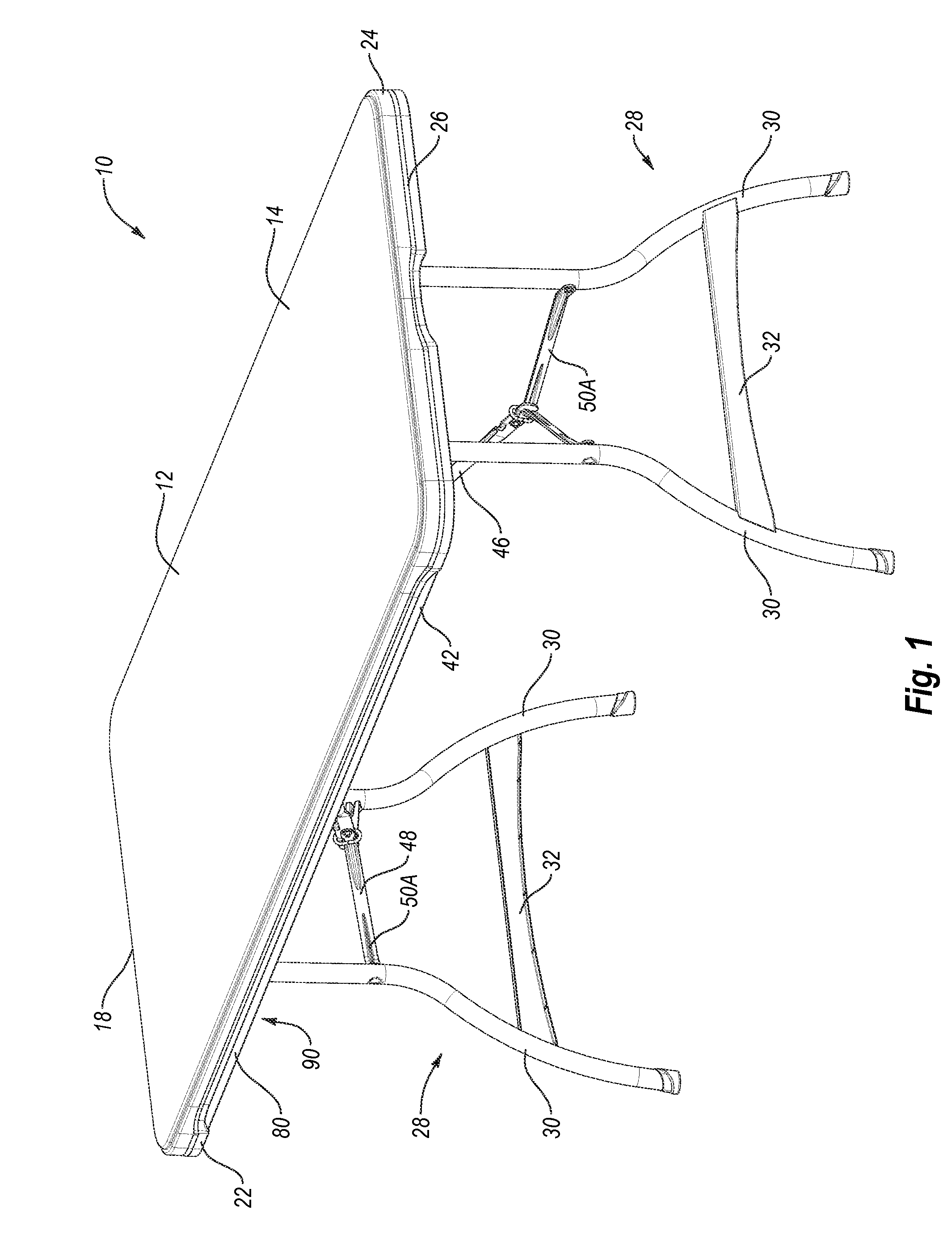
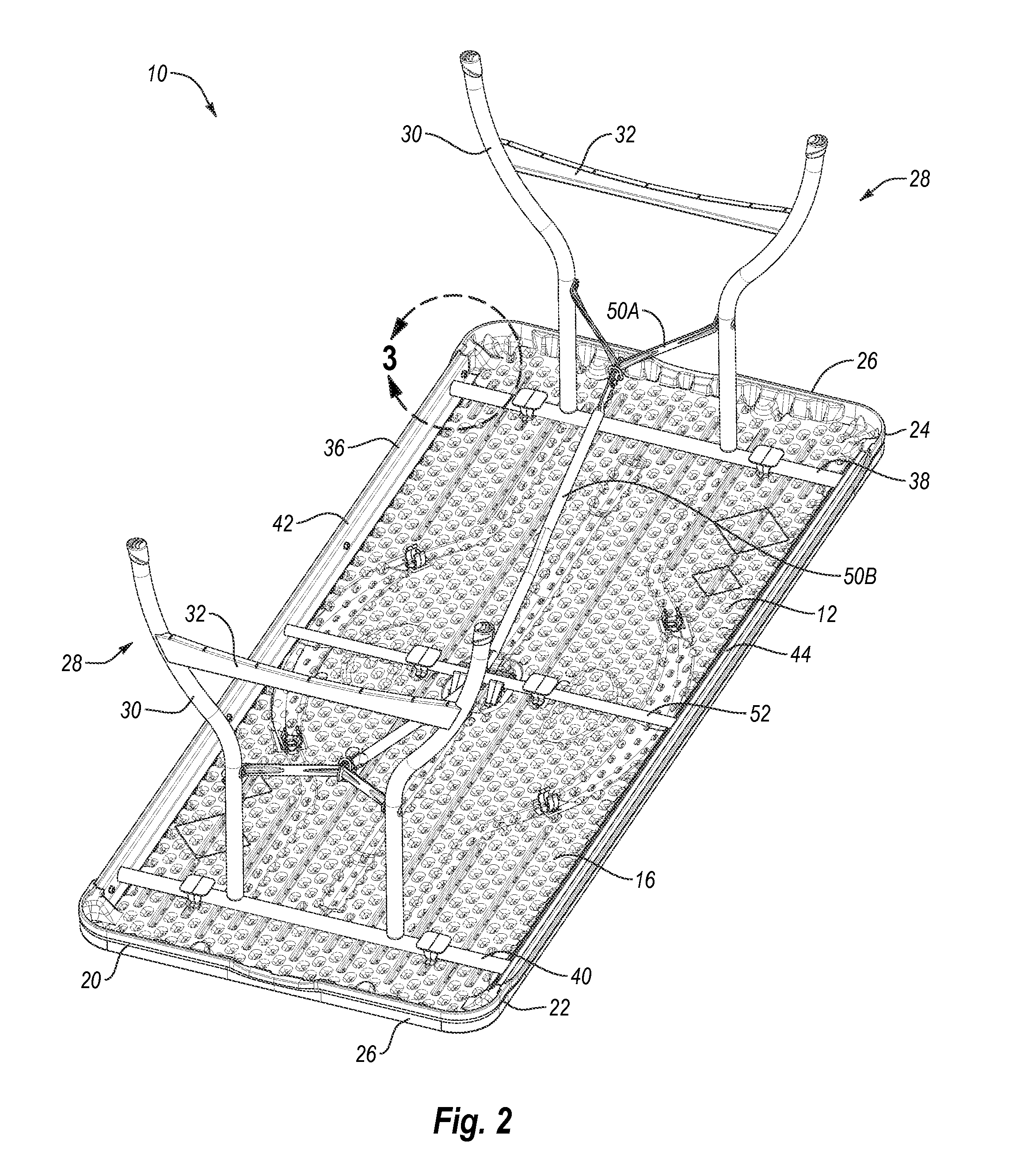
[0114]The present invention is generally directed towards tables. The principles of the present invention, however, are not limited to tables. It will be understood that, in light of the present disclosure, the tables disclosed herein can have a variety of shapes, sizes, configurations and arrangements. In addition, while the tables shown in the accompanying figures are banquet or utility tables, it will be appreciated the tables may have any suitable style or configuration such as round, personal, conference or card tables. Further, the invention disclosed herein may be successfully used in connection with other types of furniture and / or structures.

[0115]Additionally, to assist in the description of preferred embodiments of the tables, words such as top, bottom, front, rear, right and left may be used to describe the accompanying figures which may be, but are not necessarily, drawn to scale. It will further be appreciated the tables can be disposed in a variety of desired positions...


PUM


Abstract

A table may be sized and configured to nest with an adjacent table to reduce a height of a plurality of stacked tables in a nested configuration. The table may include a molded plastic table top that has a receiving portion disposed proximate an outer perimeter of the table top. The receiving portion is sized and configured to receive an engaging portion of an adjacent, nested table. The table may also include a frame with a first load bearing surface sized and configured to contact a generally planar upper surface of another adjacent, nested table. The table may further include an engaging portion sized and configured to be disposed in a receiving portion of the adjacent, nested table. The nested tables are preferably substantially identical and aligned in the stacked configuration.

Description

CROSS-REFERENCE TO RELATED APPLICATIONS[0001]The present application claims priority to and the benefit of U.S. provisional patent application Ser. No. 61 / 478,786, entitled TABLE, which was filed on Apr. 25, 2011; U.S. provisional patent application Ser. No. 61 / 478,879, entitled TABLES AND CHAIRS, which was filed on Apr. 25, 2011; U.S. design patent application Ser. No. 29 / 390,471, entitled PORTION OF A TABLE TOP, which was filed on Apr. 25, 2011; U.S. provisional patent application Ser. No. 61 / 531,081, entitled TABLE, which was filed on Sep. 5, 2011; and U.S. provisional patent application Ser. No. 61 / 543,277, entitled TABLE, which was filed on Oct. 4, 2011; each of which is hereby incorporated by reference in its entirety.BACKGROUND[0002]1. Field of the Invention[0003]The present invention generally relates to structures including at least a portion constructed from plastic and, in particular, to furniture, such as tables and chairs, that may include molded plastic components.[000...

Claims


Application Information

Patent Timeline
IPC IPC(8): A47B7/02
CPCA47B7/02A47B3/0912
Inventor PEERY, WENDELLJOHNSON, MITCHWINTER, DAVID C.
Owner HUNTER INDUSTRIES
Why Eureka
Try Eureka