Device and method for controlling internal combustion engine

a technology of internal combustion engine and control device, which is applied in the direction of electrical control, machine/engine, exhaust treatment electric control, etc., can solve the problems of incomplete oxidation reaction, difficult to completely oxidize pm discharged from the engine, and worse fuel consumption, and achieve excellent effect and effectively use ozone

a technology of internal combustion engine and control device, which is applied in the direction of electrical control, machine/engine, exhaust treatment electric control, etc., can solve the problems of incomplete oxidation reaction, difficult to completely oxidize pm discharged from the engine, and worse fuel consumption, and achieve excellent effect and effectively use ozone

US20090235648A1Inactive Publication Date: 2009-09-24TOYOTA JIDOSHA KK

Image

  • Device and method for controlling internal combustion engine
  • Device and method for controlling internal combustion engine
  • Device and method for controlling internal combustion engine

Examples


Embodiment Construction

[0027]Embodiments of the present invention will be described below with reference to the attached drawings.

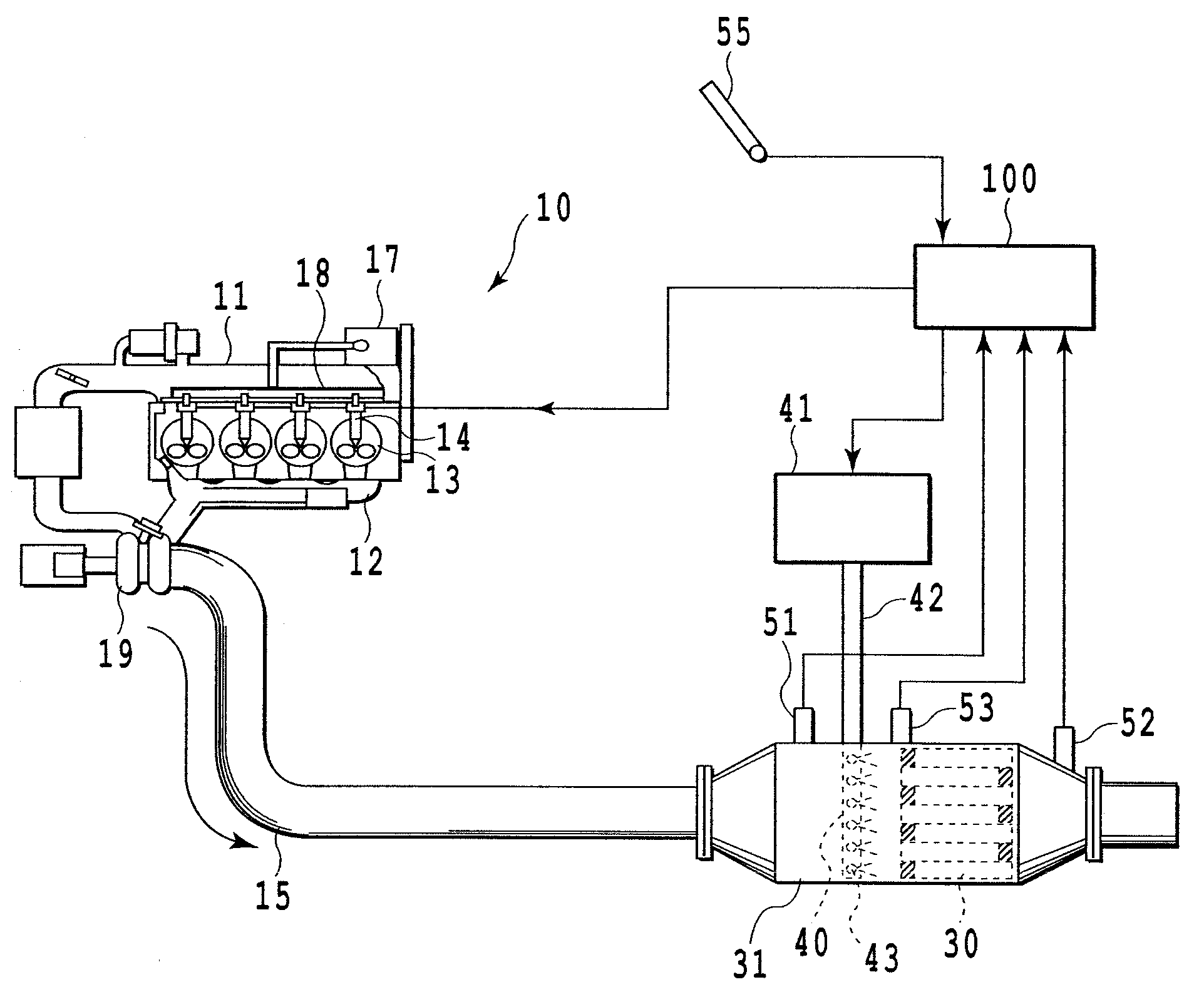
[0028]FIG. 1 is a system diagram diagrammatically illustrating a device for controlling an internal combustion engine according to an embodiment of the present invention. In the drawing, reference numeral 10 denotes an internal combustion engine of a compressive ignition type; that is, a diesel engine in a case of this embodiment. Reference numeral 11 denotes an air-intake manifold communicated with an air-intake port, 12 denotes an exhaust manifold communicated with an exhaust port, and 13 denotes a combustion chamber. In this embodiment, fuel supplied from a fuel tank not shown to a high-pressure pump 17 is pumped to a common rail 18 and accumulated there at a high pressure, which fuel in the common rail 16 is then injected into the combustion chamber 13 directly from a fuel injection valve 14. Exhaust gas from the diesel engine 10 enters the exhaust manifold 12 and then a tu...


PUM


Abstract

A device for controlling an internal combustion engine comprises a device for trapping particulate matter (PM) in exhaust gas in an exhaust passage, means for supplying ozone to the particulate matter trapping device from the upstream thereof to oxidize and remove PM deposited in the device, and means for interrupting the fuel injection of the internal combustion engine upon the execution of ozone supply by the ozone supply means. It is possible to prevent components consuming ozone, such as NOx, from being contained in the exhaust gas of the internal combustion engine, whereby ozone is effectively usable.

Description

FIELD OF TECHNOLOGY[0001]The present invention relates to a device and a method for controlling an internal combustion engine, particularly to those in which the engine comprises an exhaust gas cleaning apparatus for cleaning particulate matter in exhaust gas discharged from a diesel engine by trapping and oxidizing the particulate matter.BACKGROUND ART[0002]It has been known in general that the exhaust gas discharged from the diesel engine contains particulate matter (hereinafter referred to PM) mainly composed of carbon, causing the atmospheric contamination. Accordingly, various devices and methods have been proposed, for trapping the particulate matter and removing it from the exhaust gas.[0003]For example, there have been many proposals wherein the temperature of a diesel particulate filter (DPF) is elevated by forcibly supplying fuel by the injection so that the trapped PM is oxidized and burnt, or NO2 is generated from NO in the exhaust gas and used for oxidizing PM (see Japa...

Claims


Application Information

Patent Timeline
24 Sep 2009
Publication
US20090235648A1
IPC
F01N9/00; F01N3/10; F01N3/02
CPC
F01N3/021; F01N3/029; F01N2240/38; F01N2610/00; F02D2200/0812; F02D41/029; F02D41/123; F02D41/1466
Inventors
KAKINOHANA, MASARU; HIRATA, HIROHITO