Dimmer triggering circuit, dimmer system and dimmable device

a triggering circuit and dimmer technology, applied in the direction of electric variable regulation, process and machine control, instruments, etc., can solve the problems of inability to operate the triac-based dimmer, the dimmer does not perform properly, and consumes little power

Active Publication Date: 2009-10-08
SIGNIFY HLDG BV
View PDF15 Cites 152 Cited by
  • Summary
  • Abstract
  • Description
  • Claims
  • Application Information

AI Technical Summary

Problems solved by technology

It is widely recognized that dimmers do not perform properly if they are used in low-load dimmer applications, e.g. light sources based on a light-emitting diode (LED).
LEDs consume little power, and are therefore unable to operate the TRIAC-based dimmer as intended.
Furthermore, a dynamic load control signal is needed, which makes the dimmer system complex and difficult to implement.
Finally, the dynamic dimming load described in WO2005 / 115058 draws a current of several mA, even when not active, resulting in considerable waste of energy.
Depending on the type of dimmer used, some components need to be adapted, which makes the dimmer system inflexible.
The circuit also relies on adding a large load to the system, resulting in high current components being required in the circuit and high power loss in the system.

Method used


Image

  • Dimmer triggering circuit, dimmer system and dimmable device
  • Dimmer triggering circuit, dimmer system and dimmable device
  • Dimmer triggering circuit, dimmer system and dimmable device

Examples


Embodiment Construction

[0042]The following is a description of certain embodiments of the invention, given by way of example only.

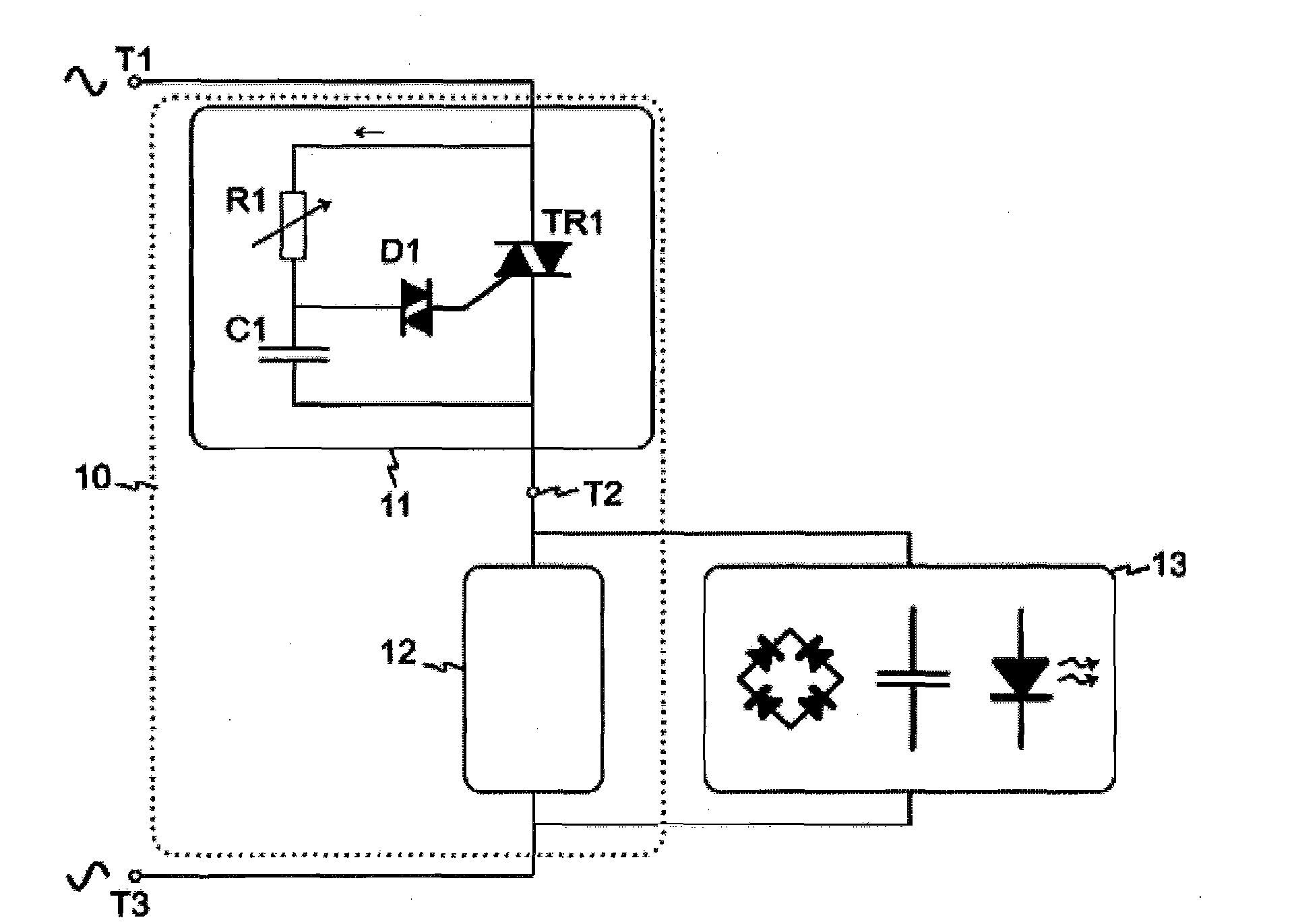
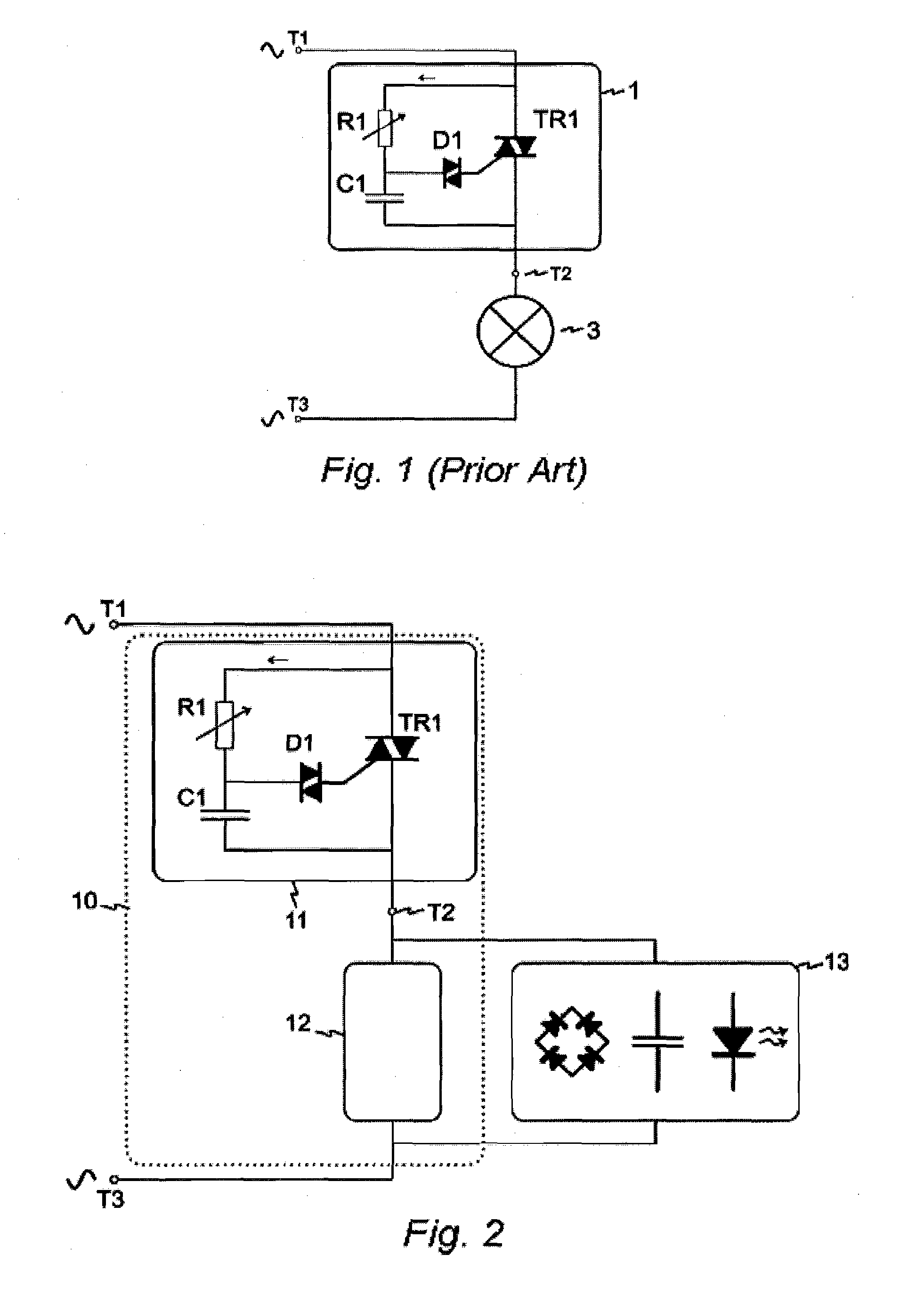
[0043]FIG. 1 schematically shows a conventional dimmer 1 in connection with an incandescent bulb 3. Note that electromagnetic interference (EMI) filter components are left out to enhance the clarity of FIG. 1. The dimmer 1 comprises a TRIAC TR1 connected in parallel with a variable resistor R1 and a capacitor C1 in series. In this description, the combination of resistor R1 and capacitor C1 will be referred to as an RC-circuit or timer circuit. Additionally, the dimmer comprises a triggering component, i.e. a component suitable to trigger the TRIAC TR1. Generally, a Diode for Alternating Current (DIAC) is used for this purpose. A DIAC is a bidirectional trigger-diode that conducts current after a DIAC threshold voltage, also referred to as the DIAC trigger voltage, has been exceeded. A DIAC remains conducting while the current flowing through it remains above a threshold curren...


PUM


Abstract

The invention relates to a dimmer triggering circuit (12) for triggering a dimmer in an alternating current network. The dimmer has a voltage-level detector (15), and a bipolar current source circuit (18). The voltage-level detector (15) detects whether an absolute value of an input voltage of the dimmer triggering circuit is below a threshold value. The bipolar current source circuit (18) provides a current if the voltage detected by the voltage-level detector (15) is below the threshold value. If the voltage detected is not below the threshold value, the bipolar current source circuit is deactivated. The dimmer triggering circuit (12), in operation, dissipates an average power less than 100 mW.

Description

BACKGROUND OF THE INVENTION[0001]1. Field of the Invention[0002]The present invention relates to a dimmer triggering circuit for low-load applications, e.g. LED-based light sources. The invention further relates to a dimmer system comprising such a dimmer triggering circuit.[0003]2. Description of the Related Art[0004]Generally, phase-controlled dimmers comprise a TRIode for Alternating Current, further referred to as a TRIAC. A TRIAC is a bidirectional switch which can conduct current in either direction when it is triggered, i.e. turned on. It can be triggered by either a positive or a negative voltage being applied to its gate electrode, i.e. when a small current is applied to its gate. This current only needs to be applied for a short period of time, i.e. in the order of microseconds. In other words, the TRIAC needs to be triggered or ‘fired’. Once triggered, the device continues to conduct until the current through it drops below a certain threshold value, such as at the end of...

Claims


Application Information

Patent Timeline
Patent Type & Authority Applications(United States)
IPC IPC(8): H05B37/02H05B44/00
CPCH05B33/0815Y02B20/347H05B39/044H05B45/3575Y02B20/00Y02B20/30Y02B20/40
Inventor VELTMAN, ANDRE
Owner SIGNIFY HLDG BV
Why Eureka
Try Eureka