Three-dimensional image display device and three-dimensional image display method

a display device and three-dimensional image technology, applied in static indicating devices, instruments, optical elements, etc., can solve the problems of difficult production of image pick-up devices that utilize different projecting methods and different projection center distances between vertical and horizontal directions, increased processing load, and inability to recognize images placed on the boundary between elemental images. , to achieve the effect of reducing the viewing zone, reducing processing speed, and high visibility

Inactive Publication Date: 2009-12-17
KK TOSHIBA
View PDF23 Cites 15 Cited by
  • Summary
  • Abstract
  • Description
  • Claims
  • Application Information

AI Technical Summary

Benefits of technology

[0013]The present invention has been made in view of these circumstances, and an object thereof is to provide a three-dimensional image display device and a three-dimensional image display method by wh...

Problems solved by technology

An image pick-up device that utilizes different projecting methods and different projection center distances between the vertical direction and the horizontal direction is difficult to produce, because cameras or lenses of the same size as the object to be displayed are required, especially in a orthographic projecting operation.
Also, since the process of inserting an alarm image...

Method used


Image

  • Three-dimensional image display device and three-dimensional image display method
  • Three-dimensional image display device and three-dimensional image display method
  • Three-dimensional image display device and three-dimensional image display method

Examples


Embodiment Construction

[0038]The following is a description of a three-dimensional image display device in accordance with an embodiment of the present invention, with reference to the accompanying drawings.

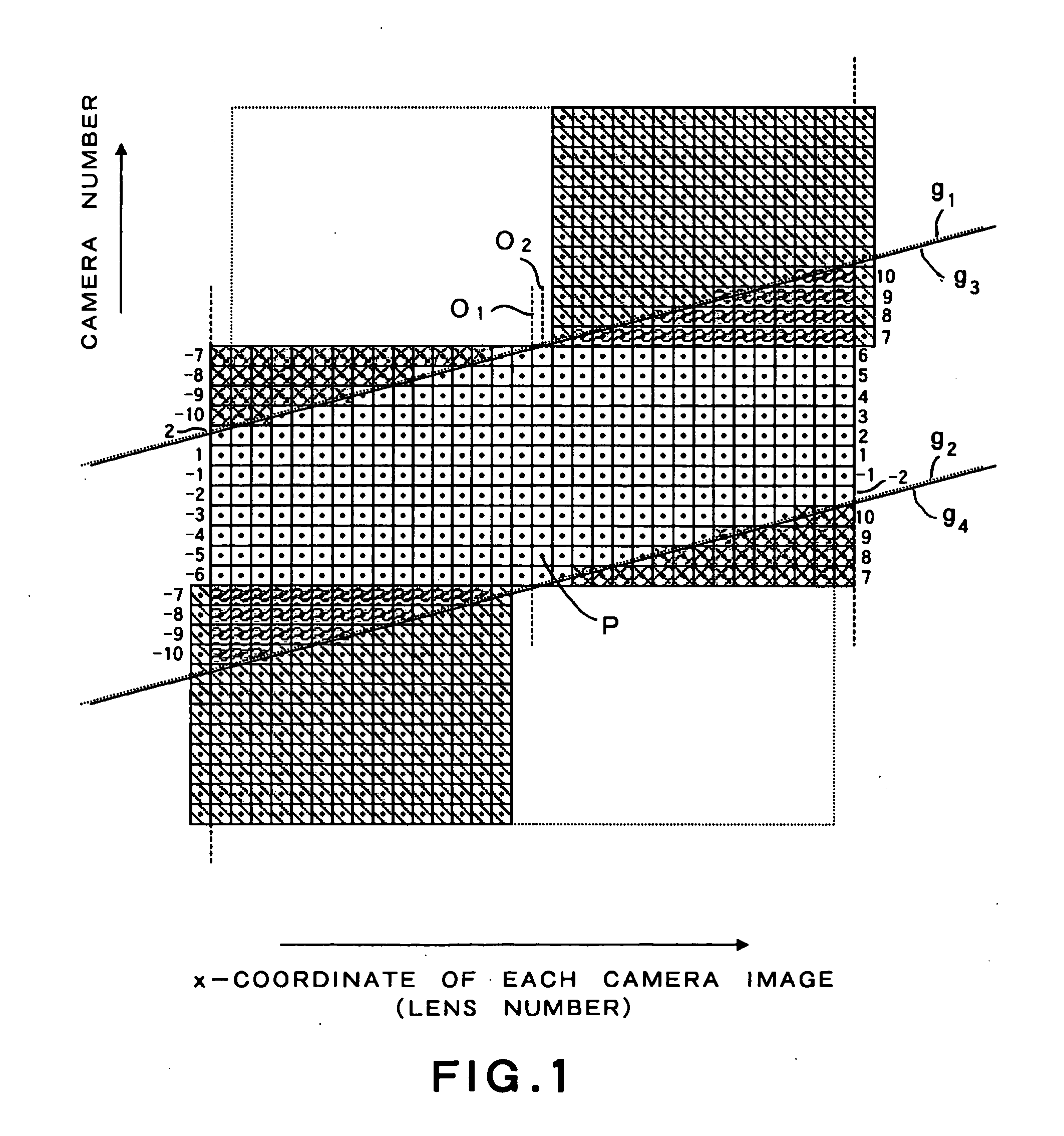
[0039]FIG. 1 is a conceptual diagram showing a data space for illustrating an image conversion method to be utilized in a three-dimensional image display device in accordance with an embodiment of the present invention. The data space shown in FIG. 1 is substantially equivalent to a generally-known light field or ray space (EPI). In FIG. 1, the abscissa axis indicates the x-coordinate of each camera image (the lens number (the number allotted to each elemental image)), and the ordinate axis indicates the camera number. The numbers shown on both sides in the ordinate direction are parallax numbers. Each one rectangle (having a dot in its center) P represents one-pixel data of a parallax component image (a camera image). One-pixel data P is shown as a data space only for one value on the vertical-directi...


PUM


Abstract

It is made possible to provide a three-dimensional image display device by which an alarm image with high visibility can be displayed at the end of the viewing zone in a parallel-ray one-dimensional IP system, without a reduction of the viewing zone or a decrease in processing speed. A three-dimensional image display device includes: an elemental image display unit that has pixels arranged in a matrix form in a display plane, and displays elemental images; an optical plate that is placed to face the elemental image display unit, has optical apertures that extend linearly in a vertical direction and are arranged at regular intervals in a horizontal direction, and controls light rays from the elemental image display unit; and an image data converting unit that converts image data so that single-color portions having periodically varying widths are inserted to boundary portions between the elemental images, the width varying with locations in the elemental image display unit, the inserted single-color portions being asymmetrical in the entire elemental image display unit.

Description

BACKGROUND OF THE INVENTION[0001]1. Field of the Invention[0002]The present invention relates to a three-dimensional image display device and a three-dimensional image display method.[0003]2. Related Art[0004]There are various known systems for stereoscopic image display devices or so-called three-dimensional display devices that can display moving images. In recent years, there is an increasing demand for flat-panel type devices that do not require any special tools such as glasses. One of the systems that can be easily realized is a system in which an optical plate for directing the light rays from a display panel (an elemental image display unit) toward a viewer is placed in front of the display panel of a device such as a liquid crystal display device or a plasma display device of a direct-vision type or a projection type having the pixel positions fixed therein.[0005]An optical plate is generally called a parallax barrier, and controls light rays so that different images can be...

Claims


Application Information

Patent Timeline
IPC IPC(8): G06T15/00G02B27/22G09G3/00G02F1/13H04N13/04
CPCH04N13/0404H04N13/0447H04N13/0409H04N13/305H04N13/31H04N13/351G03B27/22
Inventor SAISHU, TATSUOFUKUSHIMA, RIEKO
Owner KK TOSHIBA
Why Eureka
Try Eureka