Method of transmitting signals for multiple antenna system

a multi-antenna system and signal technology, applied in multiplex communication, multi-frequency code systems, polarisation/directional diversity, etc., can solve the problem that the conventional art of alamouti cannot acquire a spatial multiplexing gain irrespective, and the number of reception antennas should be higher, so as to achieve lower encoding complexity, improve communication efficiency, and improve performance

Inactive Publication Date: 2009-12-24
LG ELECTRONICS INC
View PDF1 Cites 0 Cited by
  • Summary
  • Abstract
  • Description
  • Claims
  • Application Information

AI Technical Summary

Benefits of technology

[0025]An object of the present invention is to provide a method for providing a signal for use in a multi-antenna system with an FDFR-STC code having higher performance and lower encoding complexity, and increasing communication efficiency using the FDFR-STC code.

Problems solved by technology

Basically, available frequency resources are limited under wireless communication environments.
As a result, the conventional art of Alamouti cannot acquire a spatial multiplexing gain irrespective of the number of reception antennas.
However, the above-mentioned conventional method has a disadvantage in that the number of reception antennas should be higher than the number of transmission antennas.
If a signal is wrongly recovered under the poor channel environment, the wrongly-recovered signal may unavoidably affect the next transmission signal, resulting in the deterioration of performance.
However, the above-mentioned tilted-QAM scheme cannot sufficiently acquire a coding gain, and configures a code using the combination of several data symbols, such that it has a disadvantage in that an encoding complexity unavoiably increases.

Method used


Image

  • Method of transmitting signals for multiple antenna system
  • Method of transmitting signals for multiple antenna system
  • Method of transmitting signals for multiple antenna system

Examples


first preferred embodiment

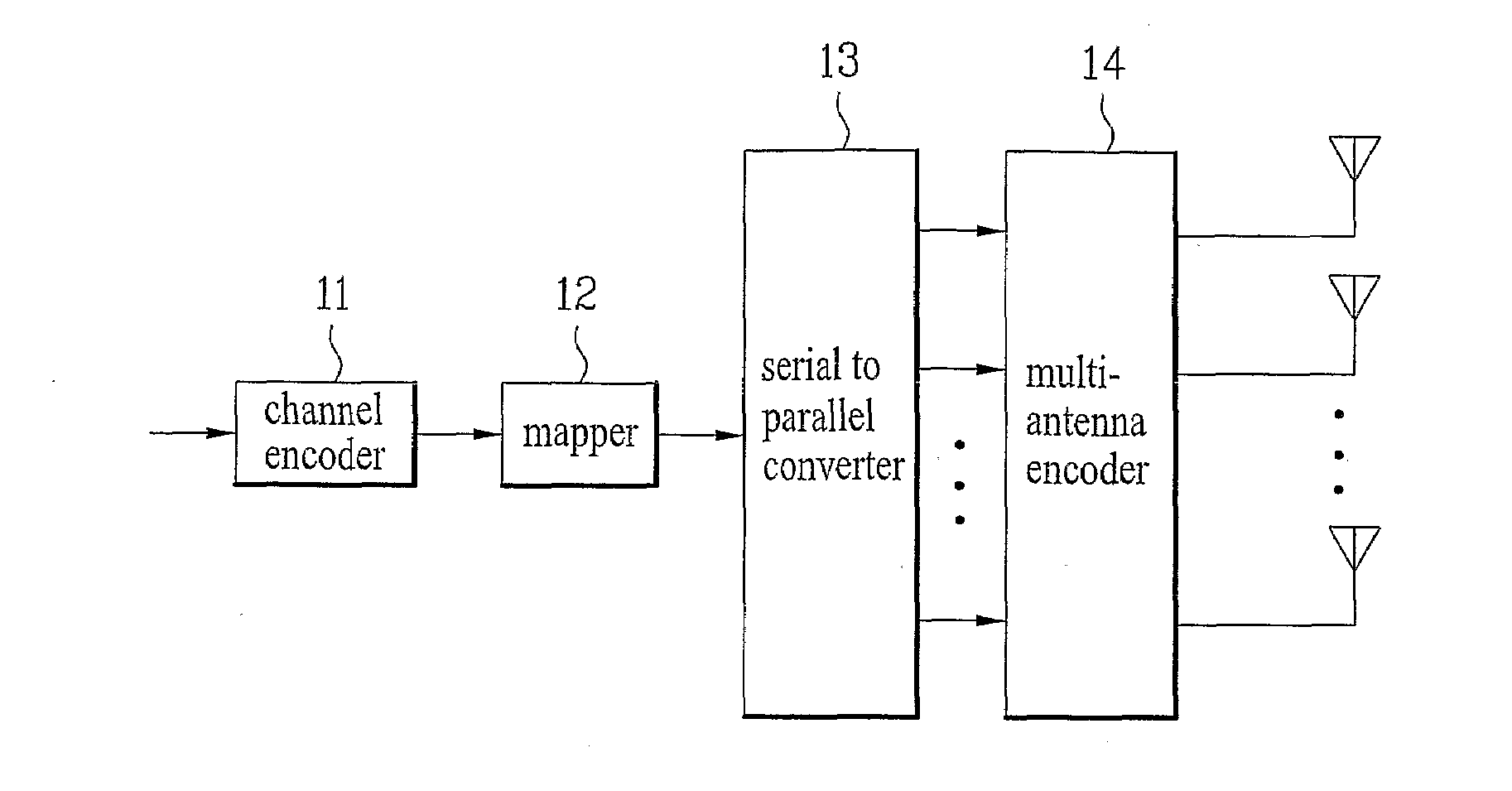
[0058]A method for generating a space-time code (STC) for acquiring a maximum multiplexing gain and a maximum diversity gain from a communication system having two transmission (Tx) antennas and two reception (Rx) antennas is explained as follows.

[0059]In other words, the above-mentioned communication system rotates individual complex data symbols on a constellation map, and performs interleaving of imaginary parts of two rotated signals to achieve a maximum diversity gain. As a result, the communication system transmits a signal via only one antenna during a single timeslot, and allows all the data symbols to acquire the maximum diversity gain.

[0060]Firstly, the space-time code (STC) can be represented by the following equation 8:

CIOD2×1=(x~100x~2)[Equation8]

[0061]In Equation 8, xi is indicative of Siejθ (where i=1 and 2), as denoted by xi=Siejθ, i=1,2, and {tilde over (x)}1 is indicative of {tilde over (x)}1=x1R+jx2R, {tilde over (x)}2=x2R+jx1R.

[0062]In order to maintain the diver...

second preferred embodiment

[0080]A pair wise error probability (PEP) of the above-mentioned LDC structure can be represented by the following equation 14:

P(c→e)≤(∏i=1Rλi)-Nr·(Es / 4N0)-R·Nr[Equation14]

[0081]In Equation 14, R is indicative of a rank of a difference matrix, and λ is indicative of an eigen value of the difference matrix. The above-mentioned difference matrix is indicative of S−E, where S is indicative of a matrix of signals transmitted from a transmission (Tx) antenna and E is indicative of an erroneous matrix.

[0082]With reference to Equation 14, R·Nr is indicative of a diversity order from among multi-antenna performances, and the product of eigen values is equal to a LDC coding gain

[0083]FIG. 5 is a graph illustrating LDC performances according to the present invention.

[0084]Referring to FIG. 5, if a diversity gain increases in a Bit Error Rate (BER) graph of a Signal to Noise Ratio (SNR), the slope increases. If the coding gain increases, it can be recognized that the graph moves to the left si...


PUM


Abstract

A signal transmission method for use in a multi-antenna system includes: receiving a complex signal using N antennas and M timeslots as a single unit, and generating a space-time code (STC) for performing interleaving and phase-shifting operations of the received complex signal; and applying the space-time code (STC) to the received complex signal, and transmitting the resultant signal. Therefore, the signal transmission method provides a space-time code (STC) provides a space-time code (STC) having higher performance and lower encoding complexity, and can effectively transmit the signal via the multi-antenna system.

Description

TECHNICAL FIELD[0001]The present invention relates to a method for transmitting a signal in a multi-antenna system, and more particularly to a method for transmitting a signal using a space-time code (STC) code having a superior performance.BACKGROUND ART[0002]In recent times, with the increasing development of information communication technologies and the widespread use of a variety of multimedia services, high-quality communication services are being developed and introduced to the market, and the demand of users who desire to use the high-quality communication services is being abruptly increased.[0003]In order to actively cope with the increasing demand of the users, capacity of a communication system must be increased. Basically, available frequency resources are limited under wireless communication environments. In order to increase communication capacity under the wireless communication environments, there is a need to more effectively use an available frequency band.[0004]I...

Claims


Application Information

Patent Timeline
Patent Type & Authority Applications(United States)
IPC IPC(8): H04L27/00H04J99/00
CPCH04B7/0669H04L1/0643H04L1/0637
Inventor IHM, BIN CHULLEE, MOON ILCHUN, JIN YOUNGLEE, WOOK BONGCHANG, JAE WONJUNG, JIN HYUK
Owner LG ELECTRONICS INC
Why Eureka
Try Eureka