Method for replacing pipes, and apparatus therefor

a technology for replacing pipes and pipes, applied in the direction of shaft lining, tunnel lining, underground chambers, etc., can solve the problems of reducing the resistance of the replacement pipe to movement through the earth, affecting the safety of workers, so as to reduce the resistance of the replacement pipe to movement, the effect of reducing the cross-sectional dimension and reducing the resistance to movemen

Active Publication Date: 2010-02-11
KOBUS SERVICES
View PDF6 Cites 0 Cited by
  • Summary
  • Abstract
  • Description
  • Claims
  • Application Information

AI Technical Summary

Benefits of technology

[0034]Preferably, the abutment surface is surrounded by a collar adapted to surround the end of the existing pipe. Desirably the collar is externally tapered so as to reduce its resistance to movement through earth.
[0035]Preferably, the comp...

Problems solved by technology

Clearly, digging a trench is an expensive and time-consuming activity, and can result in damage to the property and/or to a garden or driveway under which the existing pipe passes.
The requirement to dig a large entry and exit holes avoids much of the advantage of not digging a trench, particularly for shorter existing pipes to be replaced, and in particular creates a considerable mess within the building.
A mole cannot be used (or at least cannot be used safely) near other services such as underground electric cables.
Also, if the mole encounters an obstruction it can deviate from its cho...

Method used


Image

  • Method for replacing pipes, and apparatus therefor
  • Method for replacing pipes, and apparatus therefor

Examples


Embodiment Construction

[0036]The invention will now be described in more detail, by way of example, with reference to the accompanying drawings, in which:

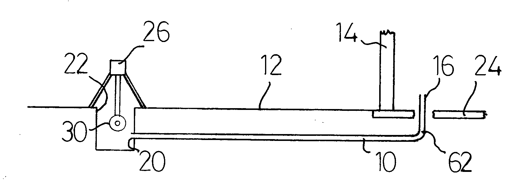
[0037]FIG. 1 shows a schematic representation of an arrangement for removing an existing pipe;

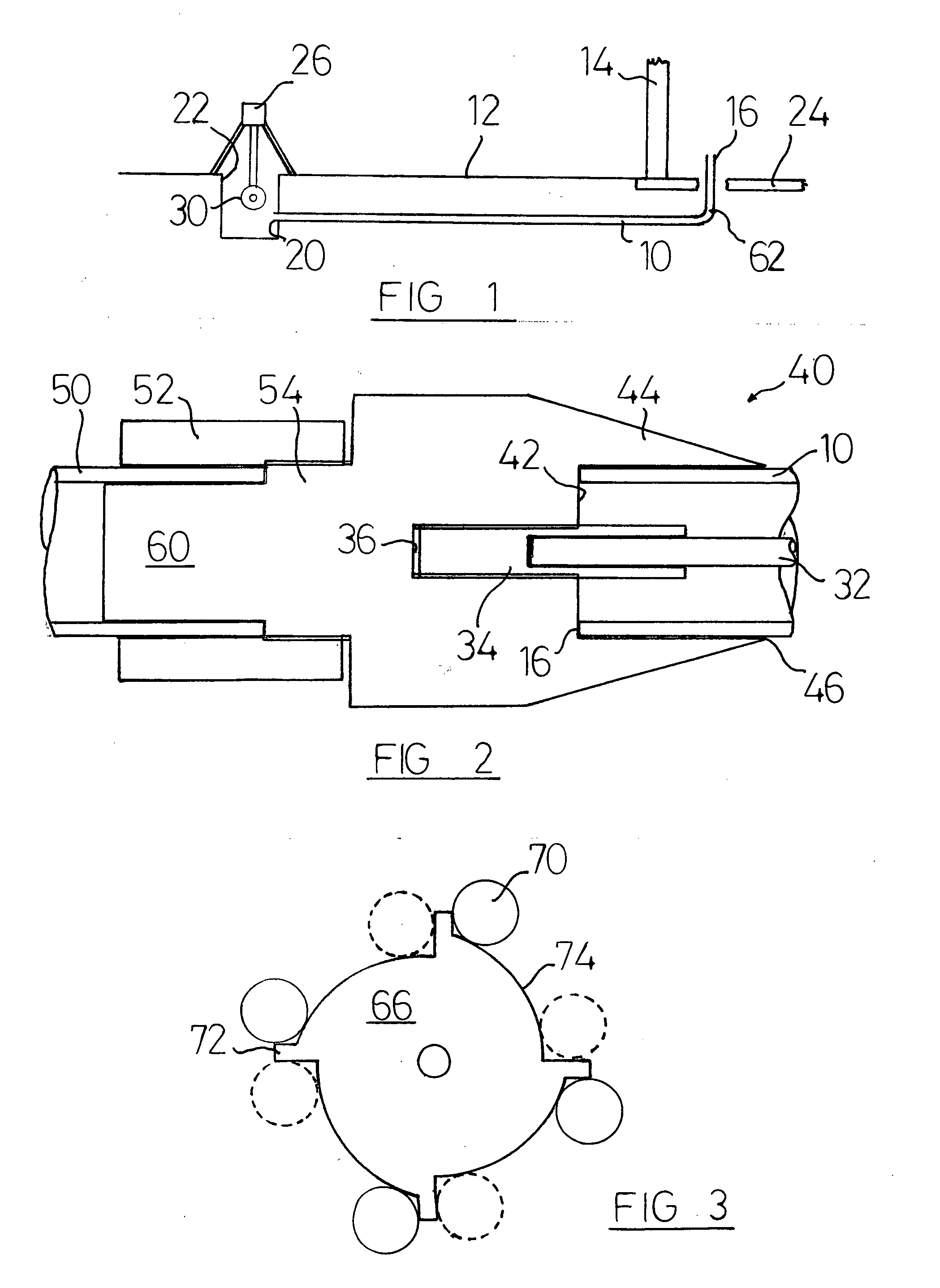
[0038]FIG. 2 shows a sectional view of one embodiment of a component fitted to the existing and replacement pipes; and

[0039]FIG. 3 shows a part of the spool of the winch mechanism.

DETAILED DESCRIPTION

[0040]The invention is adapted for use in replacing an existing pipe 10 from its location underneath the ground 12. FIG. 1 shows a typical situation in which the invention may be utilised where the existing pipe 10 is connected to the mains water supply (not shown) and is used to deliver water to a domestic dwelling, a part of an external wall 14 of the domestic dwelling being shown in FIG. 1.

[0041]The internal end 16 of the existing pipe will ordinarily be connected to the water system of the dwelling, but the pipe has been cut off adjacent its entry into the dwell...


PUM


Abstract

This invention relates to a method for replacing pipes, and an apparatus therefor. The method utilises a cable which is passed along an existing pipe. The cable is connected to a component at the end of the pipe, the component also being connected to a length of replacement pipe. The cable is pulled whereby the existing pipe is removed and the replacement pipe inserted in its place. The invention is expected to achieve its greatest utility as a method and apparatus for replacing pipes carrying water or gas to domestic and commercial properties.

Description

FIELD OF THE INVENTION[0001]This invention relates to a method for replacing pipes, and apparatus therefor. The invention is expected to achieve its greatest utility as a method and apparatus for replacing pipes carrying water or gas to domestic and commercial properties, and the following description will refer primarily to those applications. The invention is not thereby limited to these applications.BACKGROUND OF THE INVENTION[0002]Water and gas are supplied to domestic and commercial properties by way of large (mains) pipes which are laid by the utility suppliers. Smaller pipes connect the mains pipe to the individual building or dwelling. To enable the water or gas supply to be cut off from a particular building (in the event of a leak upon that property), the smaller pipes contain a valve or stopcock, the stopcock usually being located at the edge of the users property, for example at the end of the driveway serving the property.[0003]It is periodically necessary to replace th...

Claims


Application Information

Patent Timeline
IPC IPC(8): F16L55/16
CPCF16L1/032F16L55/1608F16L1/06
Inventor CILLIERS, KOBUS JACOBUS HENDRIK
Owner KOBUS SERVICES
Why Eureka
Try Eureka