This helps you quickly interpret patents by identifying the three key elements:
Problems solved by technology
Method used
Benefits of technology
Benefits of technology
[0028]The bridge faucet with side spray kit is capable of being sold with different easily replaceable components or components that may be substituted, and allows consumers to construct the bridge faucet with side spray kit into a variety of ornamental bridge faucets with side spray kits having different geometries and configurations, and allows the different mounting configurations.
[0029]The bridge faucet with side spray kit is capable of b
Problems solved by technology
Such bridge faucets and bridge faucets with side sprays having one piece faucet bodies do not facilitate easy replacement and/or substitution of opposing inlet pillars, opposing conduit arms, mixing body, and other parts and/or components when desired or required and are typically expensive to construct and/or re
Method used
Image
Click on the blue label to locate the original text in one second.
Reading with bidirectional positioning of images and text.
Examples
Example
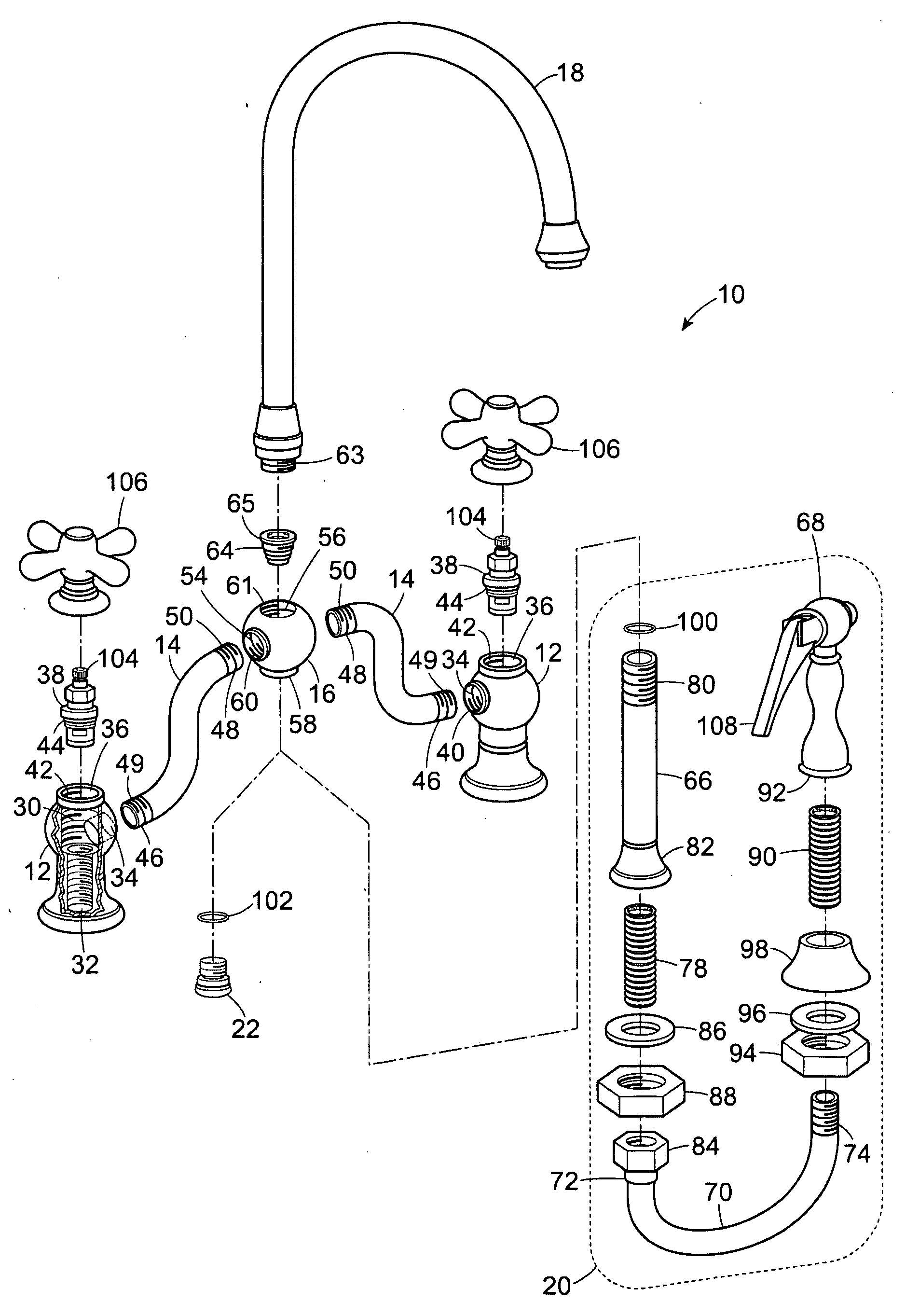
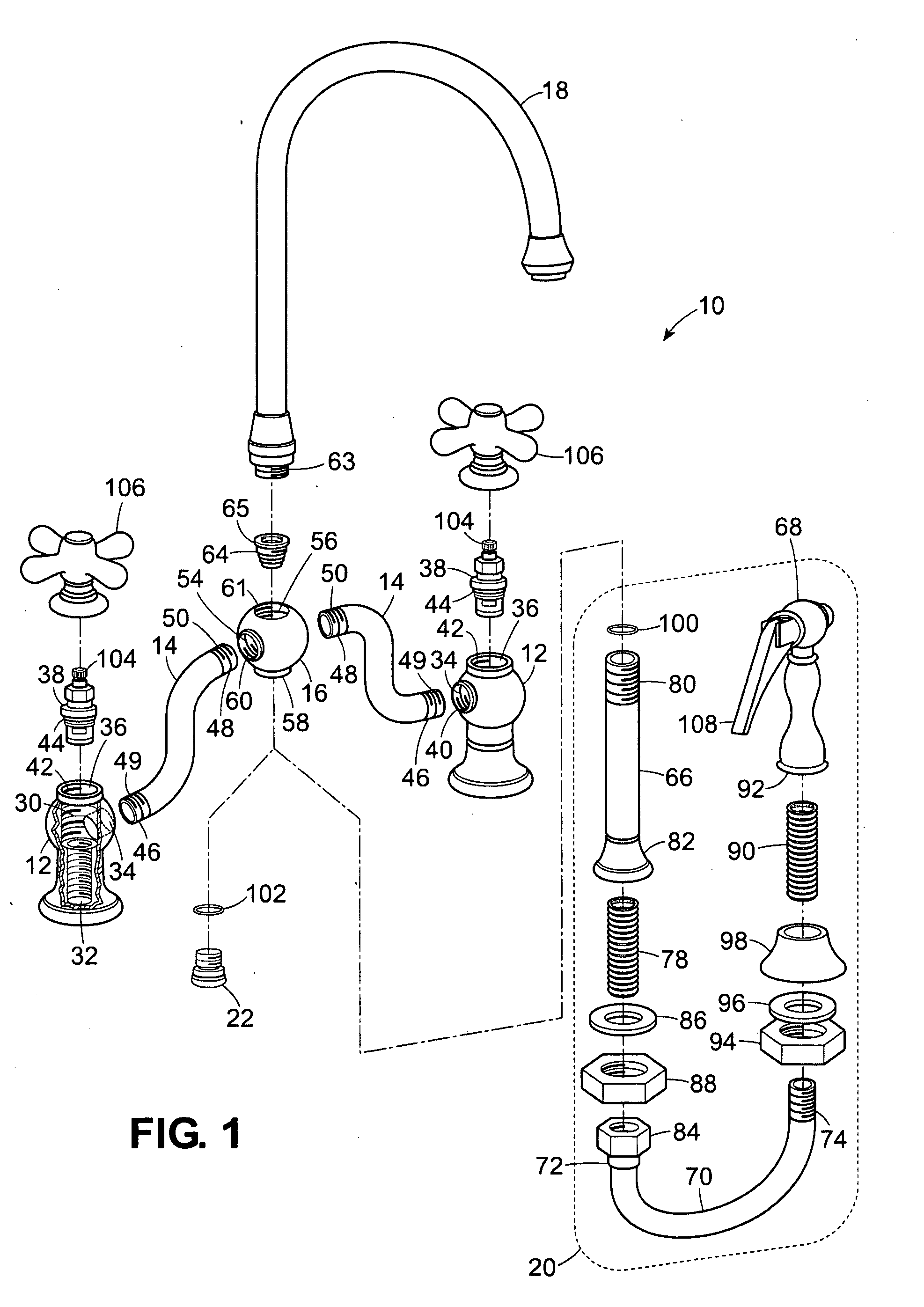
[0069]The preferred embodiments of the present invention will be described with reference to FIGS. 1-14 of the drawings. Identical elements in the various figures are identified with the same reference numbers.
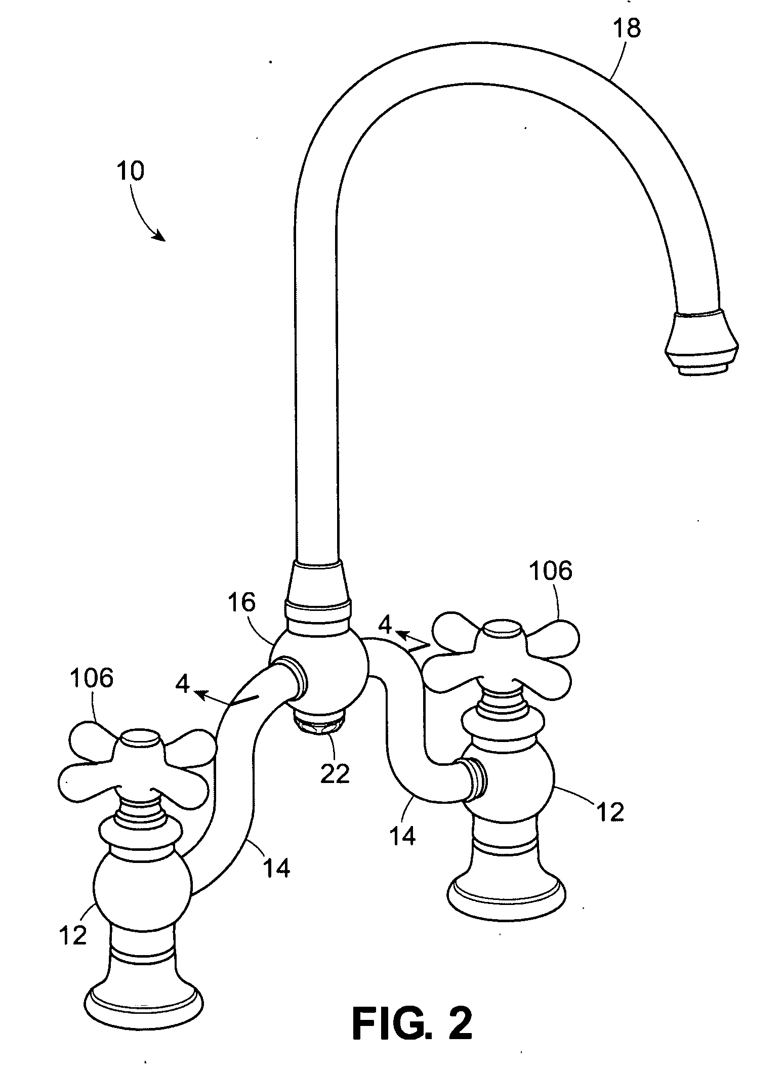
[0070]FIGS. 1-11 show an embodiment of the present invention, a bridge faucet with side spray kit 10, constructed in accordance with the present invention, comprising opposing valve bodies 12, opposing conduits 14 matingly and releasably fastened to the opposing valve bodies 12, a substantially centrally disposed mixing body 16 matingly and releasably fastened to the opposing valve bodies 12, a spout 18 matingly and releasably fastened to the substantially centrally disposed mixing body 16, a side spray kit 20, and a mixing body cap 22.
[0071]The side spray kit 20 and the mixing body cap 22 may selectively and alternatively be releasably fastened to the substantially centrally disposed mixing body 16.
[0072]Each valve body 12 of the opposing valve bodies 12 has a valve body cham...
PUM
Abstract
A bridge faucet with side spray kit of modular knockdown construction comprising removably replaceable components, including: opposing valve bodies having opposing valve body chambers, opposing conduits, substantially centrally disposed mixing body having mixing body chamber, valve body cartridge valves, mixing body diverter cartridge, spout, side spray kit, and mixing body cap, the opposing valve bodies matingly and releasably fastened to the opposing conduits, the opposing conduits matingly and releasably fastened to the substantially centrally disposed mixing body, the valve body cartridge valves adapted to matingly and removably fit into the valve body chambers, the mixing body diverter cartridge adapted to matingly and removably fit into the mixing body chamber, the side spray kit and mixing body cap selectively and alternatively matingly and removably fastened to the substantially centrally disposed mixing body, the mixing body diverter cartridge preventing water from flowing into the spout when the side spray kit is used.
Description
[0001]This application is a continuation-in-part of U.S. patent application Ser. No. 29 / 323,407, filed Aug. 25, 2008, and this application is a continuation-in-part of U.S. patent application Ser. No. 29 / 323,410, filed Aug. 25, 2008, and this application is a continuation-in-part of U.S. patent application Ser. No. 29 / 323,412, filed Aug. 26, 2008, and this application is a continuation-in-part of U.S. patent application Ser. No. 29 / 323,414, filed Aug. 26, 2008, and this application is a continuation-in-part of U.S. patent application Ser. No. 29 / 323,415, filed Aug. 26, 2008, and this application is a continuation-in-part of U.S. patent application Ser. No. 29 / 323,416, filed Aug. 26, 2008, the full disclosures of which all are incorporated herein by reference. The above referenced documents are not admitted to be prior art with respect to the present invention by their mention herein.BACKGROUND OF THE INVENTION[0002]1. Field of the Invention[0003]The present invention relates general...
Claims
Application Information
Patent Timeline
Application Date:The date an application was filed.
Publication Date:The date a patent or application was officially published.
First Publication Date:The earliest publication date of a patent with the same application number.
Issue Date:Publication date of the patent grant document.
PCT Entry Date:The Entry date of PCT National Phase.
Estimated Expiry Date:The statutory expiry date of a patent right according to the Patent Law, and it is the longest term of protection that the patent right can achieve without the termination of the patent right due to other reasons(Term extension factor has been taken into account ).
Invalid Date:Actual expiry date is based on effective date or publication date of legal transaction data of invalid patent.

