

Permanent magnet motor and washing machine provided therewith
- Summary
- Abstract
- Description
- Claims
- Application Information
AI Technical Summary
Benefits of technology
Problems solved by technology
Method used
Image

Examples
first embodiment
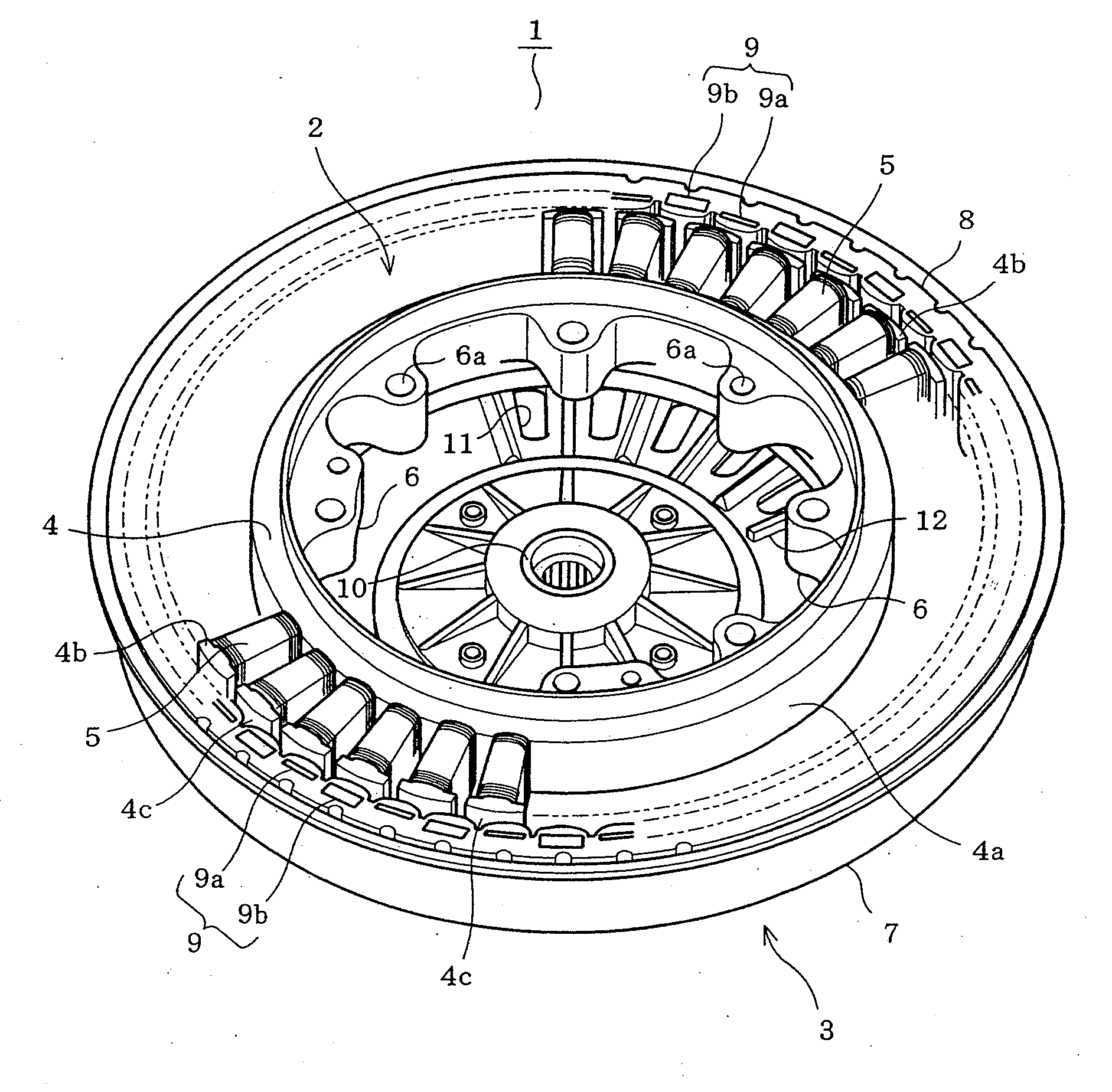
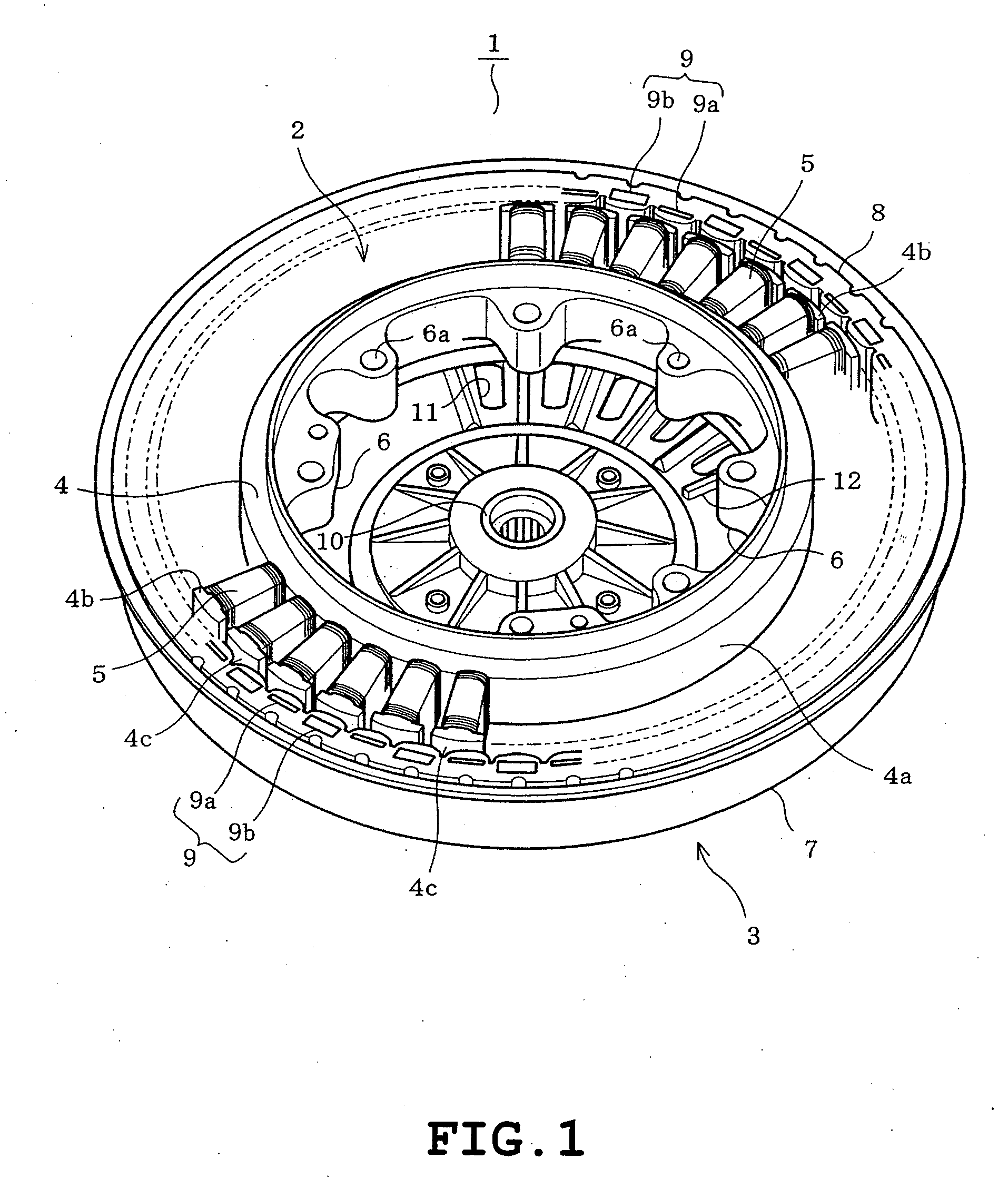
[0025]the present invention will be described with reference to FIGS. 1 to 7 of the accompanying drawings. Referring to FIG. 1, an entire construction of a permanent magnet motor 1 (a brushless motor of the outer rotor type) of the embodiment is shown. The permanent magnet motor 1 comprises a stator 2 and a rotor 3 provided along an outer circumference of the stator 2. The stator 2 comprises a stator core 4 and a plurality of stator windings 5. The stator core 4 is formed by stacking and pressing a number of silicon steel plates serving as a punched soft magnetic material. The stator core 4 includes an annular yoke 4a and a number of teeth 4b protruding radially from an outer circumference of the yoke 4a. The stator core 4 has a surface covered with a polyethylene terephthalate (PET) resin (molded resin) except for outer circumferential faces 4c which cooperate with an inner circumference of the rotor 3 thereby to define a gap there between. Furthermore, a plurality of mounting port...
third embodiment
[0060]Each alnico magnet 9d has a magnetic characteristic approximate to those of each samarium-cobalt magnet 9b and each neodymium magnet 9c (see solid line Q in FIG. 5 and solid line R in FIG. 9). Accordingly, the construction of the third embodiment can also render the variations in the flux content larger and minimize the ratio of winding current necessary for change in the flux content to the variations in an amount of magnetic flux.
[0061]A fourth embodiment of the invention will be described with reference to FIGS. 11 and 12. The fourth embodiment will be described with respect to the same construction (using the neodymium magnets 9c instead of the samarium-cobalt magnets 9b) as in the second embodiment with reference to the relationship between the magnetic polarization and the field intensity of the neodymium magnets 9c, but not the relationship between the flux density and the field intensity of the neodymium magnets 9c.
fourth embodiment
[0062]Firstly, the magnetic characteristic will be described in the case where the neodymium magnets 9c are demagnetized, with reference to FIG. 11 showing the relationship between the magnetic polarization and the field intensity of the neodymium magnets 9c. Solid line J in FIG. 11 denotes a hysteresis loop (major loop) from a saturated magnetic polarization (Js) of the neodymium magnets 9c to a saturated magnetic polarization (−Js) at the opposed pole. In FIG. 11, solid line j1 denotes a hysteresis loop (minor loop) from point R1 present in a second quadrant in the major loop J to the point S1 present in a first quadrant in the major loop J through point T1 at the magnetization side (the right side in FIG. 11). When the neodymium magnets 9c are demagnetized, an operating point of the neodymium magnets 9c is displaced along the minor loop J1 in the first and second quadrants in the
[0063]Point R1 is an arbitrary point in a section between point Js (where field intensity is at 0 and ...
PUM
 Abstract
Description
Claims
Application Information