Modular ramp system

Active Publication Date: 2010-03-04
MAPP MICHAEL
View PDF31 Cites 11 Cited by
  • Summary
  • Abstract
  • Description
  • Claims
  • Application Information

AI Technical Summary

Benefits of technology

[0046]It is a still further object of the present invention to provide a table with an integral coping to enhance safety and reliability.
[0047]It is a yet further object of the present

Problems solved by technology

However, although Applicant's commercialized and patented ramp is a popular product, it is a product that may only effectively be used by itself because it was never designed to interface with other kinds of skateboarding surfaces that have evolved over the years.
Not every municipality, however, has the financial means or the land area to provide skate parks for their citizens.
However, Applicant is unaware of any prior art teaching combining together a variety of skateboarding components in the unique ways contemplated herein.
Beck et al. fail to teach or suggest the use of curved and other non-straight track sect

Method used


Image

  • Modular ramp system
  • Modular ramp system
  • Modular ramp system

Examples


Embodiment Construction

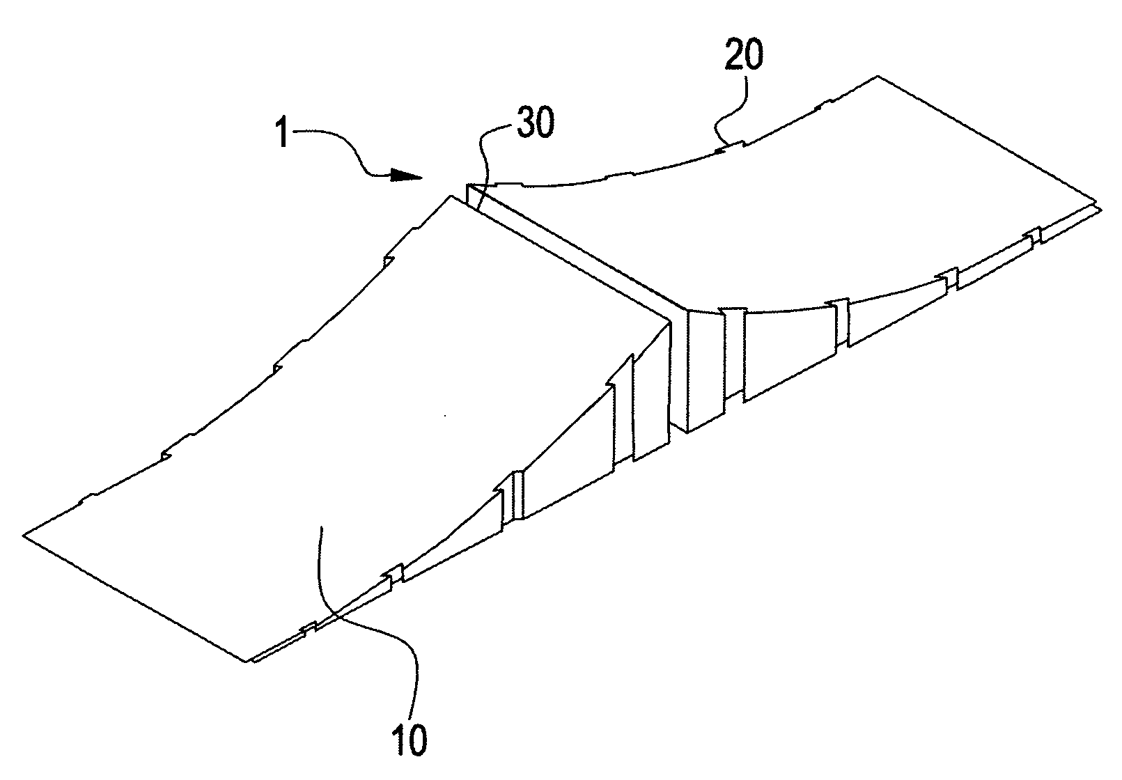
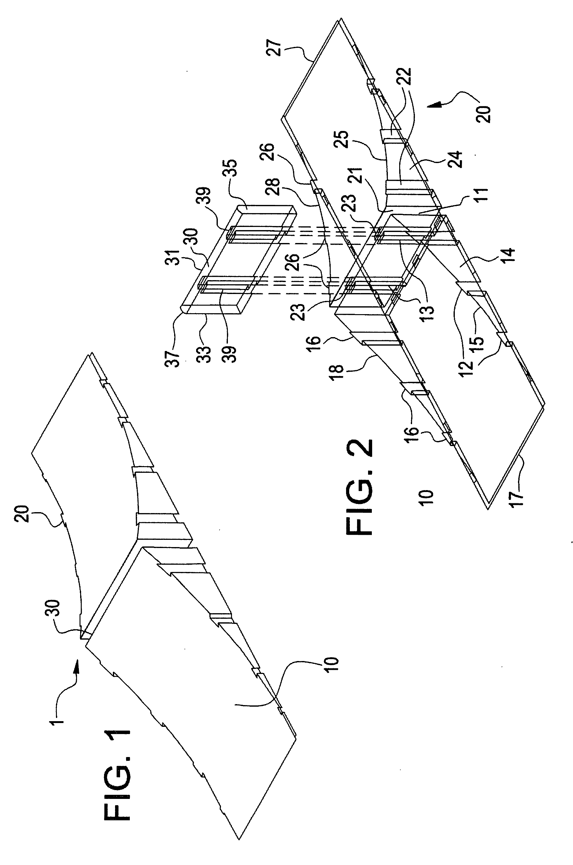
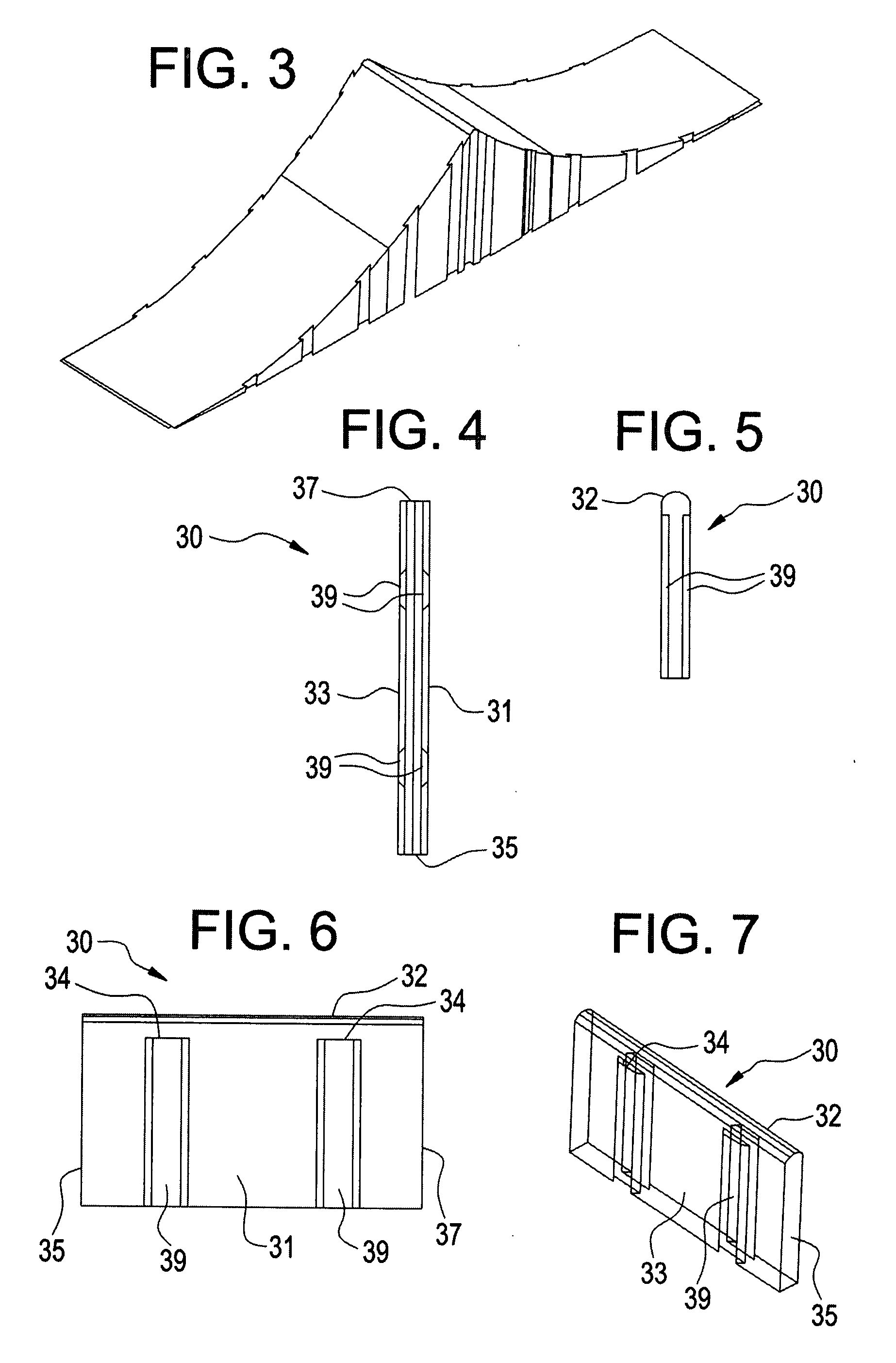
[0090]Reference is first made to FIGS. 1-7 so that a first aspect of the present invention may be disclosed in detail. With particular reference, first, to FIGS. 1 and 2, it is seen that a first ramp 10 and a second ramp 20 are oriented with rear walls or faces 11 and 21, respectively, facing one another. As best seen in FIG. 2, the rear walls or faces 11 and 21, while facing one another, are spaced apart in parallel planes. Each of the rear walls or faces 11 and 21 of the ramps 10 and 20 has connector halves comprising rearwardly extending dovetail projections generally designated by the reference numerals 13 and 23, with each ramp having two such dovetail projections extending outwardly from the rear faces thereof. Corresponding structure is also seen with particular reference to FIG. 11 which will be described in greater detail hereinafter.

[0091]The ramps 10 and 20 have radiused ramp surfaces 15 and 25, respectively, as well as forward edges 17 and 27, respectively. The ramps 10 ...


PUM


Abstract

A modular ramp system contemplates two molded plastic ramps placed back-to-back with one another so that in a direction of travel, one would travel up one ramp and then immediately down the other. The ramps are interconnected by a spine including connectors interfacing with connectors provided on the facing surfaces of the ramps. In the preferred embodiment, the connectors consist of dovetail recesses and dovetail projections. The ramps also have connection structure on their lateral sides, so that other ramps may be assembled to the two back-to-back ramps to make a ramp that is incrementally wider. The ramp may consist of a plurality of ramp sections assembled together to create a ramp. A table is designed to be used with ramps and other components and includes openings to facilitate installation of a grind rail or a support rail. The table surface includes peripheral coping integrally formed with the table during manufacture. A grind rail system includes support legs with arcuate bottoms to facilitate safe support of a grind rail regardless of angulation. Curved sections of grind rails allow lateral and vertical curvature of an elongated grind rail configuration. Connectors are provided to interconnect adjacent grind rail sections.

Description

BACKGROUND OF THE INVENTION[0001]The present invention relates to improvements in a modular ramp system. Ramp components of a variety of kinds are well known in the prior art for use by skateboarders. Angled ramps, radiused ramps, tables, quarterpipes, halfpipes, rails and other components are generally well known for use by skateboarders riding skateboards who enjoy skating on such devices for recreation as well as for competition. Applicant is the patentee of U.S. Pat. No. 5,946,756 that issued Sep. 7, 1999, and was later reissued as Reissue Pat. No. RE 38,326 on Sep. 25, 2003. Applicant's prior patent and reissue patent disclose a molded plastic ramp made in a one step molding process and including a smooth radiused ramp surface. The invention disclosed in Applicant's prior patent and reissue patent was successfully commercialized and remains one of the most popular ramps in the marketplace today. Its combination of portability, high strength, radiused ramp surface, and easy acce...

Claims


Application Information

Patent Timeline
IPC IPC(8): E01D1/00
CPCE01C13/003A63C19/10
Inventor MAPP, MICHAEL
Owner MAPP MICHAEL
Why Eureka
Try Eureka