

Apparatus for estimating tire wear amount and a vehicle on which the apparatus for estimating tire wear is mounted
- Summary
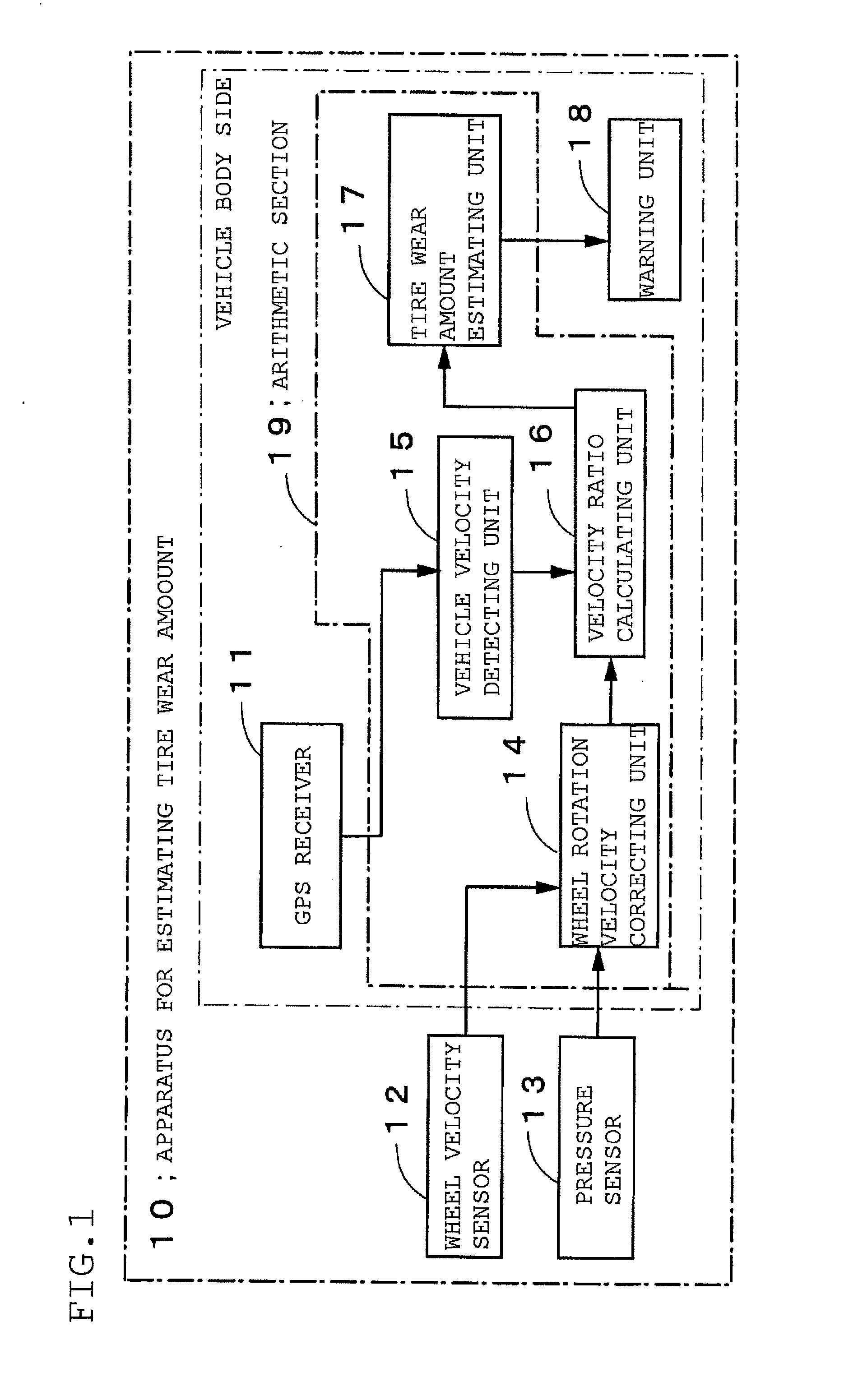
- Abstract
- Description
- Claims
- Application Information
AI Technical Summary
Benefits of technology
Problems solved by technology
Method used
Image


Examples
example 2
[0056]The vehicle on which the apparatus for estimating wear amount is mounted as shown in the embodiment 2 was run on even asphalt road at 60 h / km and then vehicle longitudinal acceleration ax and wheel rotation velocity Vw0 at 0.2 G of vehicle acceleration. A tire used in the test was 225 / 55R17 and vehicle velocity V and wheel rotation velocity Vw0 were detected with respect to each of wear at a new tire (wear amount is zero), wear in middle period (wear amount is middle) or wear in latter period (wear amount was great and rest of groove is 2 mm). Also, to consider inner pressure dependence, relation tire inner pressure and wheel rotation velocity of the new tire was examined within general inner pressure range (150, 200 and 250 kPa). The FIG. 3 shows the result. As understood in the graph, since wheel rotation velocity depends on inner pressure, it is effective to correct measured wheel rotation velocity by tire inner pressure.
[0057]According to the tire used in the test, correct...
PUM
 Abstract
Description
Claims
Application Information