Stereoscopic display device, system and method

a liquid crystal display and stereoscopic technology, applied in optics, instruments, electrical equipment, etc., can solve the problems of increased manufacturing costs and inconvenien

Active Publication Date: 2010-03-18
WISTRON CORP
View PDF4 Cites 18 Cited by
  • Summary
  • Abstract
  • Description
  • Claims
  • Application Information

AI Technical Summary

Benefits of technology

[0022]The effect of the present invention resides in that the objective of stereoscopic display c...

Problems solved by technology

However, since the conventional stereoscopic display system 9 utilizes the liquid crystal screen 90 that has the micro phase retardation film 91 additionally attached thereto in order to produce a stereoscopic display effect in conjunction with the use of the stereoscopic glasses 92, the manufacture of the ste...

Method used


Image

  • Stereoscopic display device, system and method
  • Stereoscopic display device, system and method
  • Stereoscopic display device, system and method

Examples


Embodiment Construction

[0030]Before the present invention is described in greater detail, it should be noted that like elements are denoted by the same reference numerals throughout the disclosure.

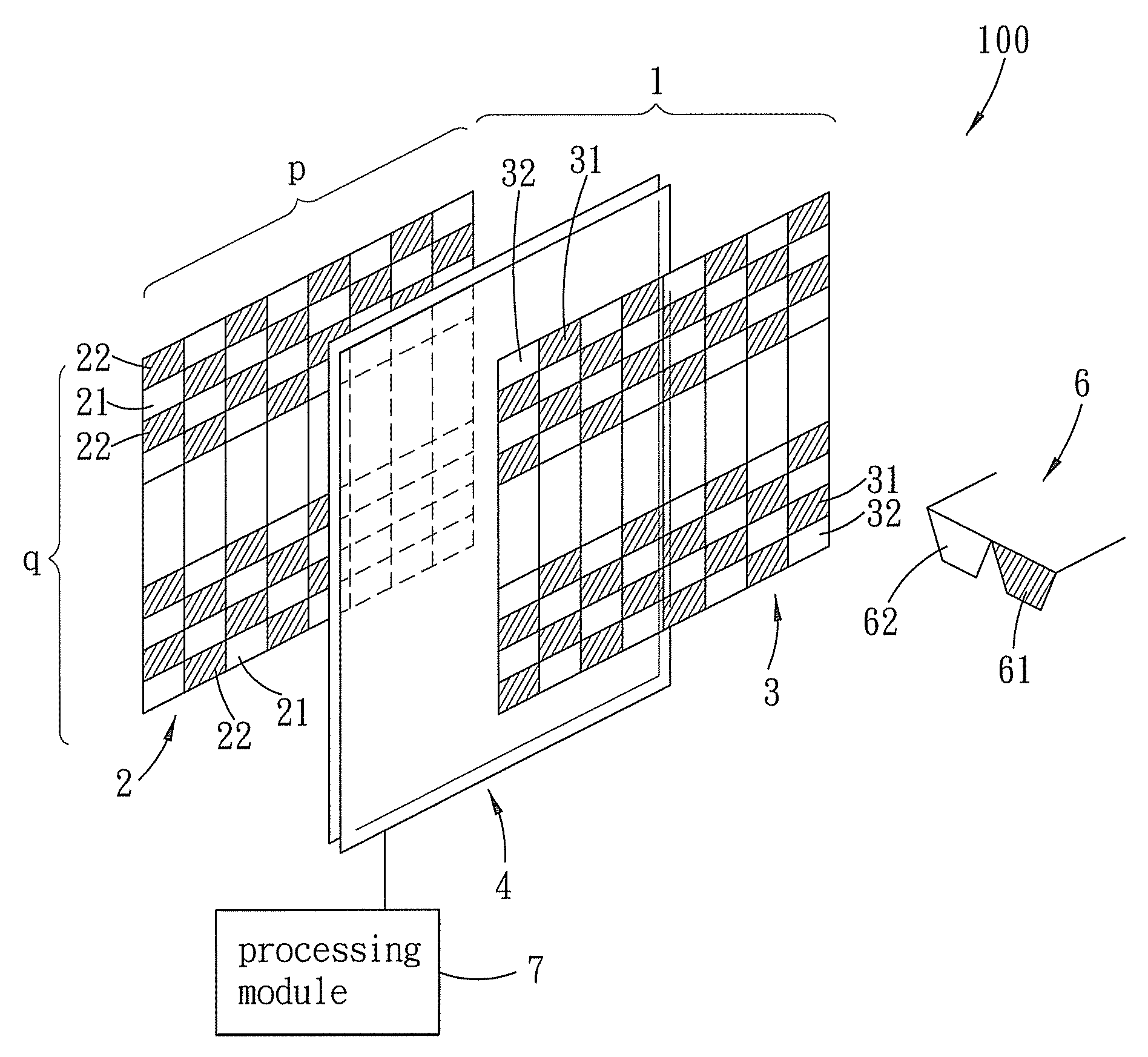
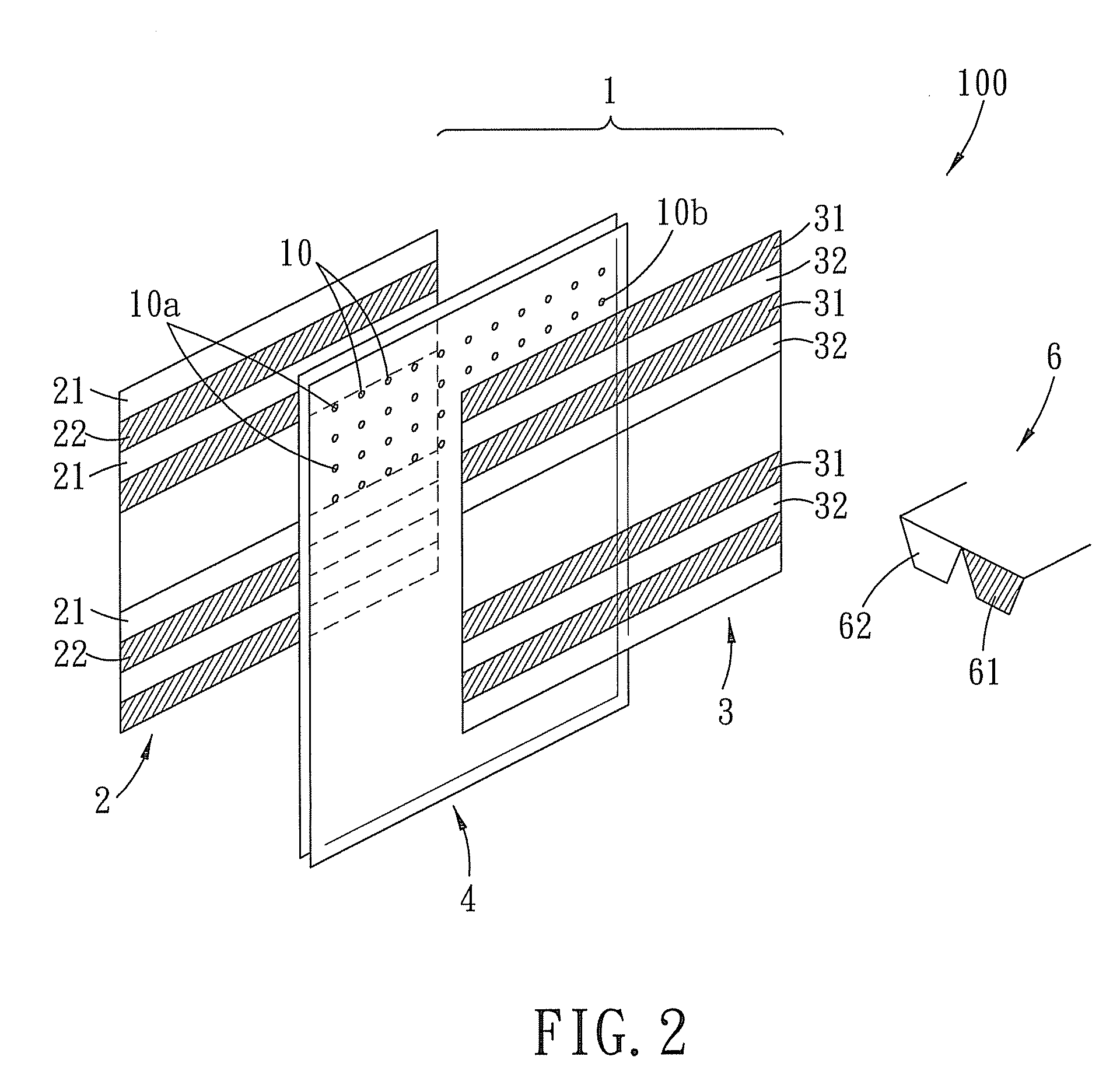
[0031]FIG. 2 schematically illustrates a stereoscopic display system 100 according to the invention. The stereoscopic display system 100 includes a stereoscopic display device 1 and stereoscopic glasses 6. The stereoscopic display device 1 is depicted in detail in FIG. 3, and includes a backlight module 5 for emitting a light beam, an inner polarizer 2 disposed proximate to the backlight module 5 for receiving the light beam emitted by the backlight module 5, an outer polarizer 3 spaced apart from the inner polarizer 2, and a display substrate panel 4 interposed between the inner and outer polarizers 2, 3. The display substrate panel 4 is a component currently used in a conventional liquid crystal display, and includes, arranged in sequence from the outside to the inside, a pair of glass substrates 41 having pix...


PUM


Abstract

A stereoscopic display device includes an inner polarizer, an outer polarizer, and a display substrate panel interposed between the inner and outer polarizers. The inner polarizer has first and second polarization regions arranged alternately and having a 90-degree polarization angle difference. The outer polarizer has third and fourth polarization regions corresponding in position to the first and second polarization regions. The third and first polarization regions have a 90-degree polarization angle difference. The fourth and second polarization regions have a 90-degree polarization angle difference. Light passing through the first polarization regions, the display substrate panel, and the third polarization regions can pass through one lens of a pair of stereoscopic glasses, whereas light passing through the second polarization regions, the display substrate panel, and the fourth polarization regions can pass through the other lens of the stereoscopic glasses.

Description

CROSS-REFERENCE TO RELATED APPLICATION[0001]This application claims priority of Taiwanese Application No. 097135795, filed on Sep. 18, 2008.BACKGROUND OF THE INVENTION[0002]1. Field of the Invention[0003]The invention relates to a stereoscopic display technique for a liquid crystal display device, more particularly to a stereoscopic display technique that can be used to produce stereoscopic effects by modifying polarizers of a liquid crystal display device.[0004]2. Description of the Related Art[0005]In order to enable a flat screen to present a stereoscopic effect, the principle of stereoscopic vision has to be employed. In other words, an image intended to be seen with the left eye should be transmitted to the left eye, and an image intended to be seen with the right eye should be transmitted to the right eye so that, after processing by the brain, stereoscopic images will be formed in the brain.[0006]For three-dimensional motion pictures, they can be produced using the principle ...

Claims


Application Information

Patent Timeline
IPC IPC(8): G02B27/26G02F1/1335H04N13/04G02B30/25
CPCG02B27/26G02F1/1323G02F1/133615H04N13/0497G02F2001/133538H04N13/0434H04N13/0486G02F2001/133531H04N13/337H04N13/315H04N13/398G02B30/25G02F1/133538G02F1/133531
Inventor CHANG, YAO-TSUNG
Owner WISTRON CORP
Why Eureka
Try Eureka