Valve Having a Sealing Member

a valve and sealing technology, applied in the direction of lift valves, slide valves, functional valve types, etc., can solve the problems of high closing speed and opening speed that can be realized by means of pneumatic actuators, affecting the longevity of seals, and reducing the service life of seals, so as to achieve the fastest possible closing stroke, high closing pressure, and simple design

Inactive Publication Date: 2010-05-13
VAT HLDG AG
View PDF14 Cites 4 Cited by
  • Summary
  • Abstract
  • Description
  • Claims
  • Application Information

AI Technical Summary

Benefits of technology

[0009]It is the object of the invention to provide a simple design with as few moving parts as possible for a valve of the generic type in which the fastest possible closing stroke can be realized and high closing pressures can be achieved in the closed position with actuators having relatively small dimensions.

Problems solved by technology

Such shear stresses on the seals are generally acknowledged as being very detrimental to the longevity of the seal.
First, the closing speed and opening speed that can be realized by means of these pneumatic actuators is not as high as would be desirable especially in the first movement phase.
Second, the dimensions and design of these actuators must be very large in order to provide the desired closing pressures in the closed position of the closure member.
However, the construction shown in this reference is relatively complicated and requires many parts.

Method used


Image

  • Valve Having a Sealing Member
  • Valve Having a Sealing Member
  • Valve Having a Sealing Member

Examples


Embodiment Construction

[0021]It is to be understood that the figures and descriptions of the present invention have been simplified to illustrate elements that are relevant for a clear understanding of the present invention, while eliminating, for purposes of clarity, many other elements which are conventional in this art. Those of ordinary skill in the art will recognize that other elements are desirable for implementing the present invention. However, because such elements are well known in the art, and because they do not facilitate a better understanding of the present invention, a discussion of such elements is not provided herein.

[0022]The present invention will now be described in detail on the basis of exemplary embodiments.

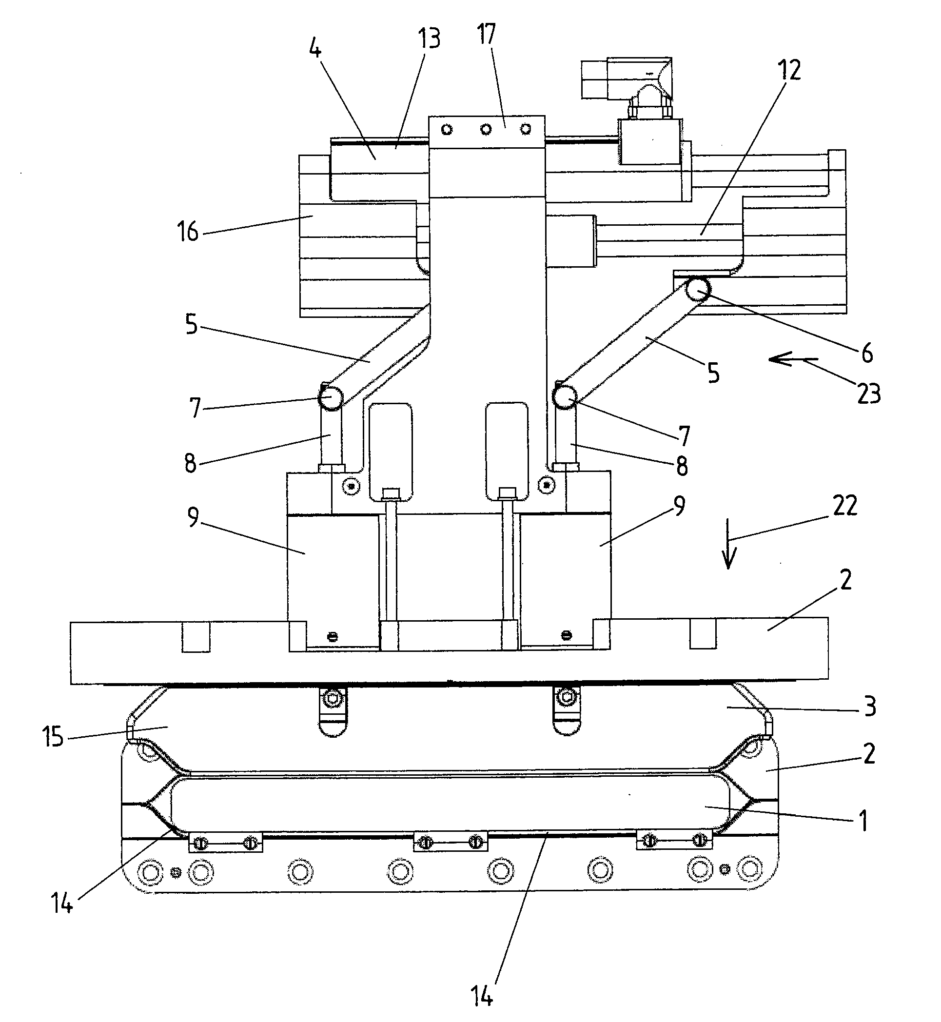
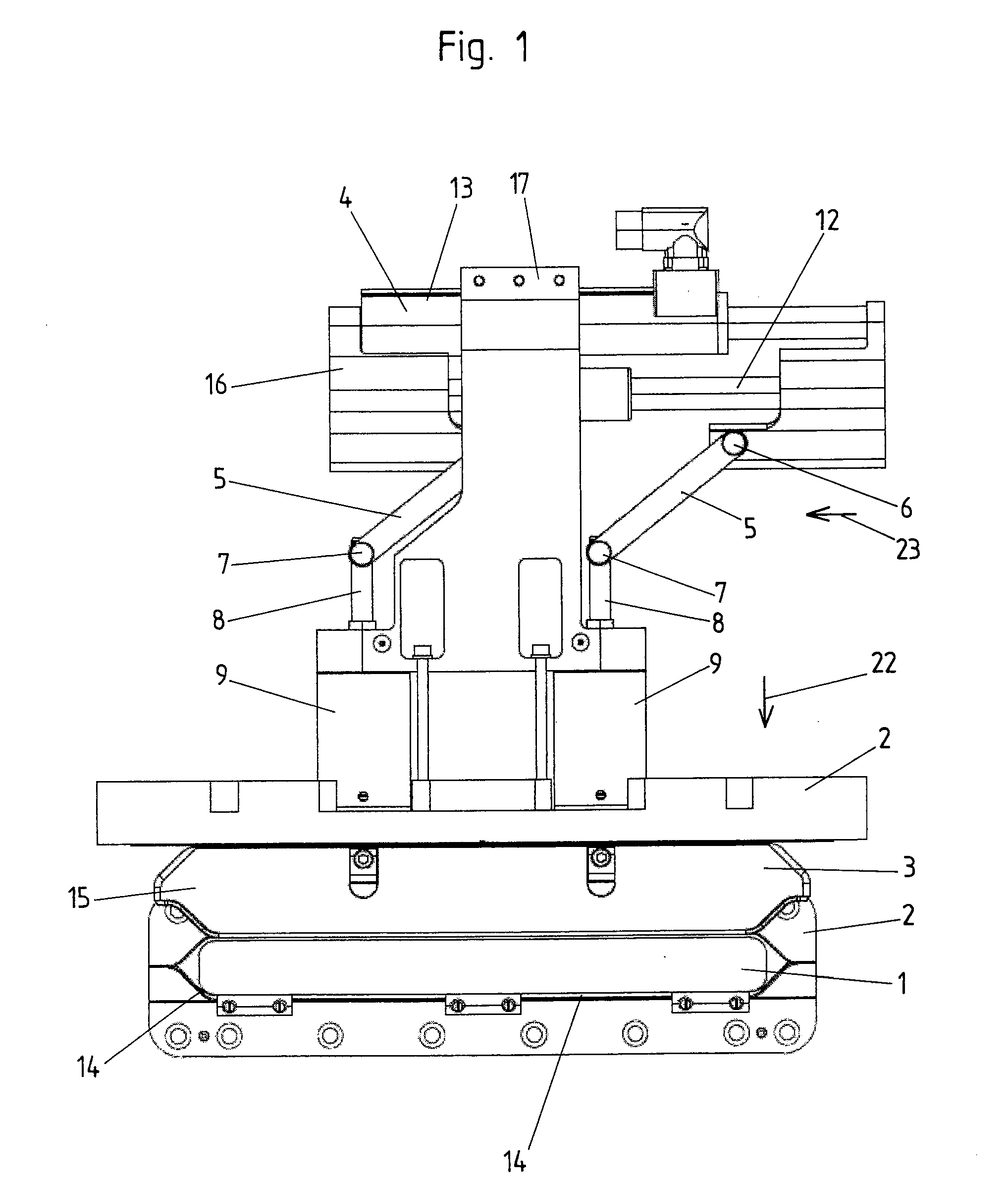
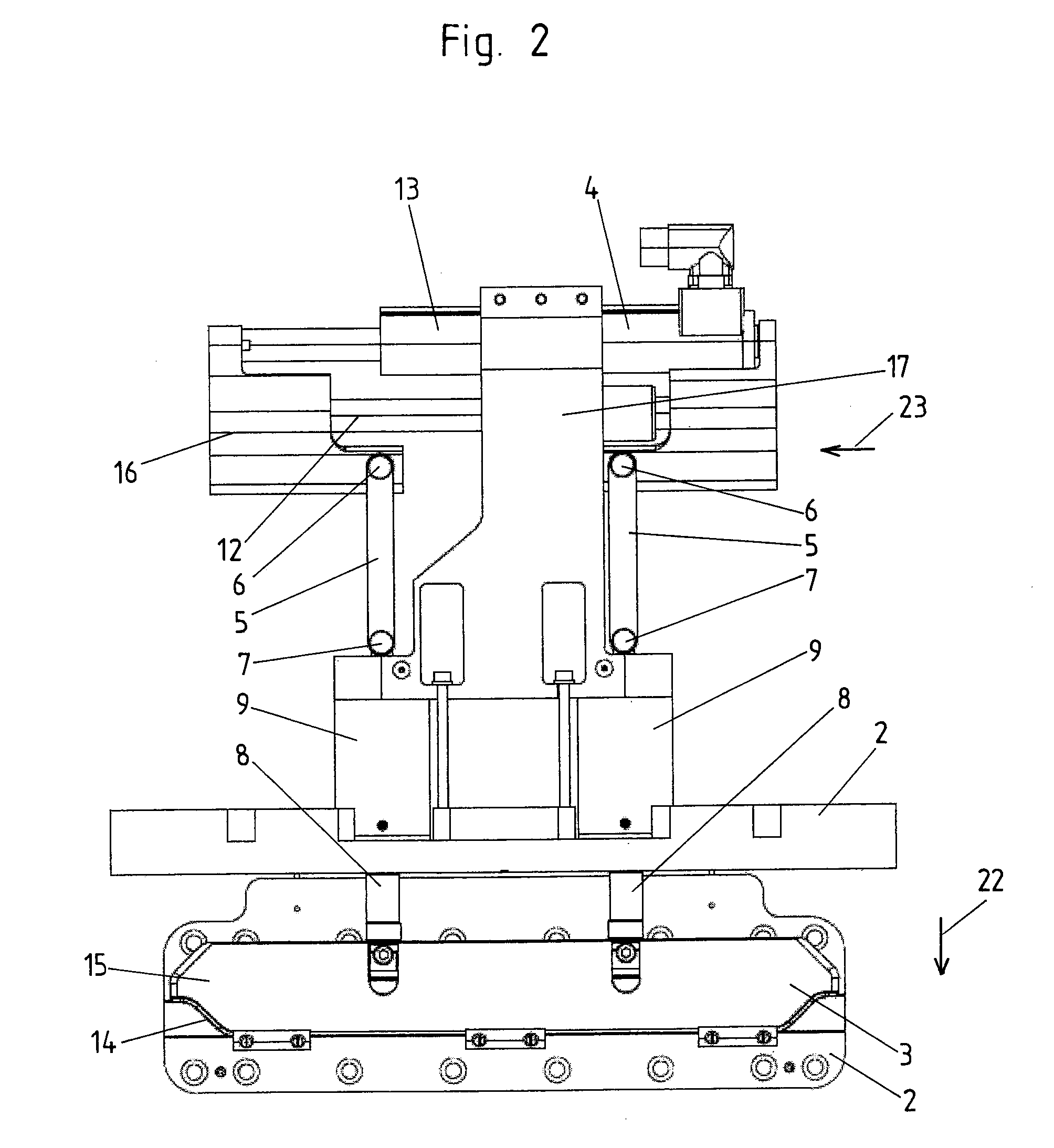
[0023]In the first embodiment example according to the invention, the closure member 3 is constructed in the form of a valve plate 15. During the movement from the maximum open position shown in FIG. 1 to the closed position shown in FIGS. 2 and 3, the valve plate 15 exclusivel...


PUM


Abstract

A valve has a closure member for closing a valve orifice, particularly so as to be tight against gas, in a closed position of the closure member. The closure member can be moved in a closing process by at least one actuator starting from a first position of maximum opening at least along a first partial distance with a linear movement component in direction of its closed position, and the actuator carries out a closing stroke with a linear stroke direction for a movement of the closure member with this movement component. The actuator is so arranged in relation to the closure member that an angle diverging from 0° and 180° is provided between the linear movement component of the closure member along the first partial distance, proceeding from the first position of maximum opening, and the linear stroke direction of the actuator.

Description

[0001]The present application is a continuation of PCT Patent Application No. PCT / EP2008 / 003168 filed on Apr. 19, 2008, which claims priority from German Patent Application No. 10 2007 023 339.8 filed on May 16, 2007, the disclosure of which is incorporated herein by reference in its entirety.BACKGROUND OF THE INVENTION[0002]1. Field of the Invention[0003]The present invention is directed to a valve having a closure member for closing a valve orifice, particularly so as to be tight against gas, in a closed position of the closure member, wherein the closure member can be moved in a closing process by at least one actuator starting from a first position of maximum opening at least along a first partial distance with a linear movement component in direction of its closed position, and the actuator carries out a closing stroke with a linear stroke direction for a movement of the closure member with this movement component.[0004]2. Description of Related Art[0005]Generic valves are used...

Claims


Application Information

Patent Timeline
Patent Type & Authority Applications(United States)
IPC IPC(8): F16K1/00
CPCF16K51/02F16K3/182F16K3/314F16K31/04F16K31/54
Inventor GANTNER, URSLITSCHER, BERNHARD
Owner VAT HLDG AG
Why Eureka
Try Eureka