Media cassette

a cassette and media technology, applied in the field of media cassettes, can solve the problems of increasing cost, affecting the reliability of the installation of the cassette, and the inability to pick banknotes reliably from the cassette,

a cassette and media technology, applied in the field of media cassettes, can solve the problems of increasing cost, affecting the reliability of the installation of the cassette, and the inability to pick banknotes reliably from the cassette,

US20100156035A1Active Publication Date: 2010-06-24NCR CORP

Image

  • Media cassette
  • Media cassette
  • Media cassette

Examples


second embodiment

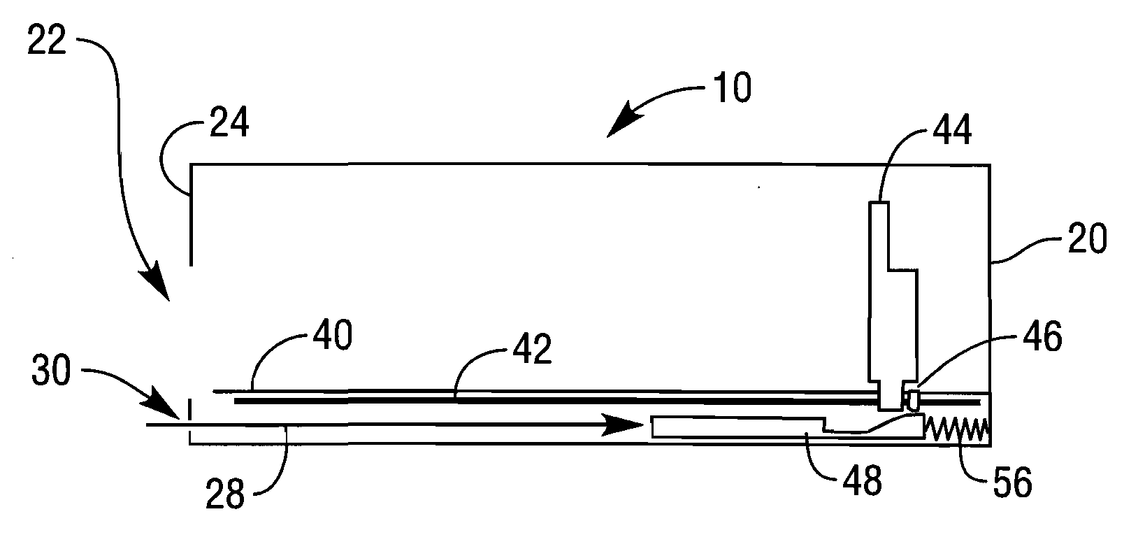
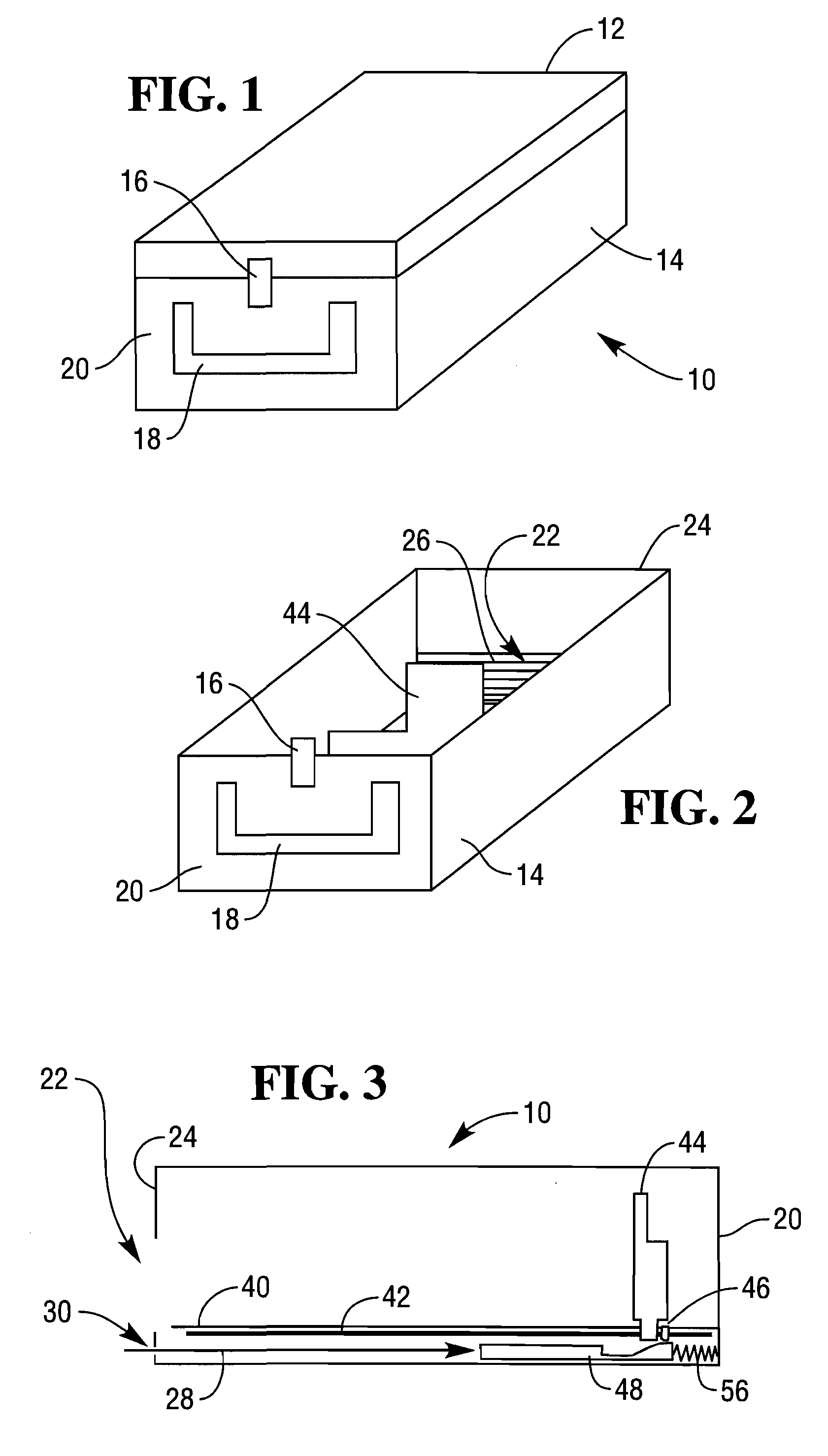
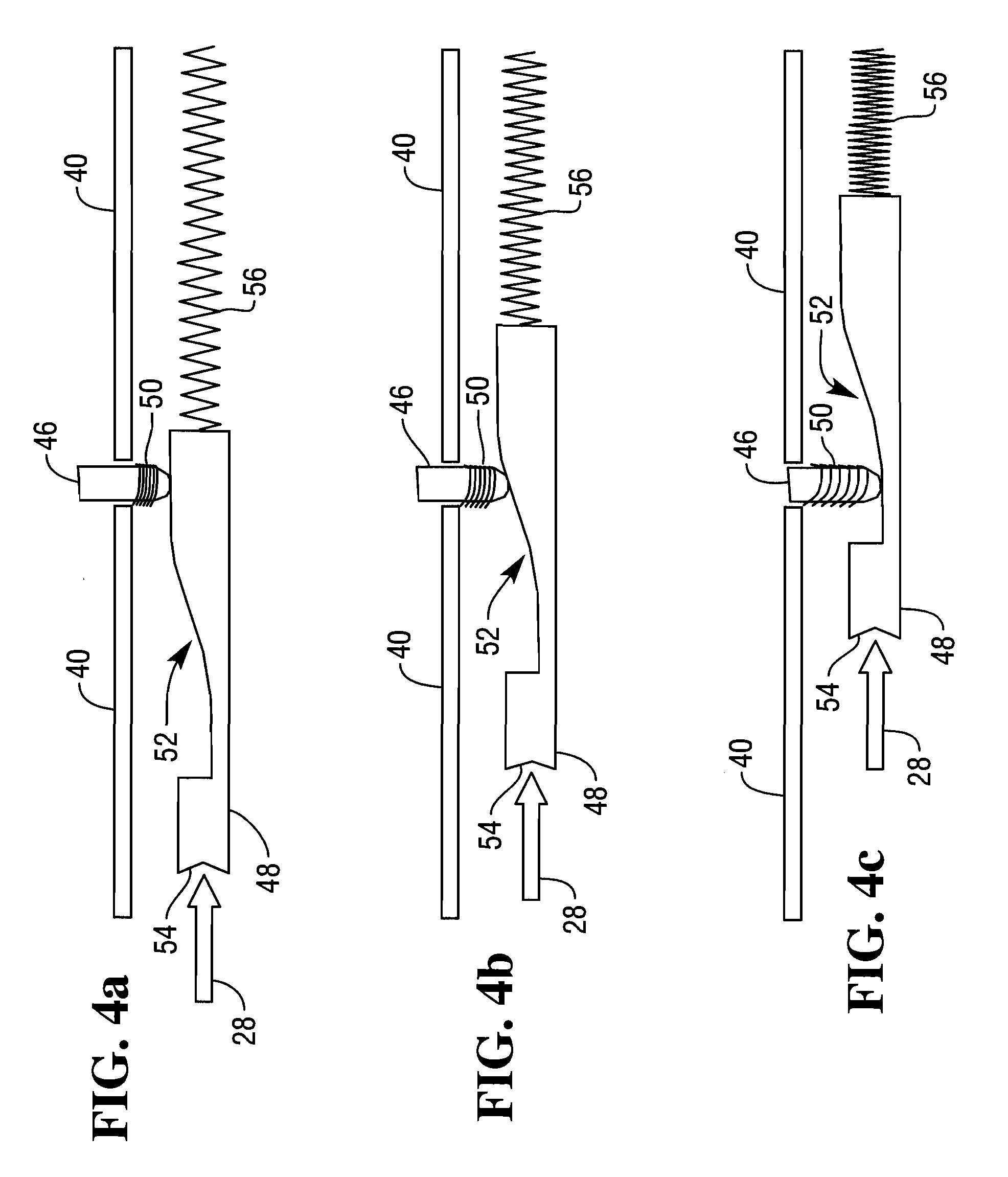
[0048]Another embodiment of the present invention will now be described with reference to FIGS. 6 to 9, which illustrate a currency cassette 100 with a detent moving mechanism mounted in a lid of the currency cassette 100.

[0049]The cassette 100 has a lid 112 secured to a body 114 by a latch 116. The body 114 has a handle 118 at a handle end 120 (a “non-picking end”), and a closed pick window 122 at the opposite end 124 (a “picking end”).

[0050]The picking end 124 includes a roller shutter 126 covering the pick window 122 when the currency cassette 100 is being transported.

[0051]The cassette 100 includes a floor 140, beneath which a central rail 142 is provided that extends longitudinally along the cassette 100 from the non-picking end 120 to the picking end 124. A biased urging plate 144 is mounted on the central rail 142 and coupled thereto by a ratchet mechanism (not shown). The urging plate 144 urges a stack of banknotes towards the pick window 122, so that when the pick window 12...


PUM


Abstract

A media cassette includes a body having a removable lid. The media cassette comprises a housing defining a closeable pick window; an urging plate biased towards the pick window for urging a stack of media items towards the pick window; a detent located distal from the pick window for limiting movement of the urging plate; and a detent moving mechanism operable to move the detent. The detent moving mechanism may be operated by engaging the removable lid or by insertion of the cassette into a media handler. The media cassette allows the urging plate to exert less force on the stack of media items by expanding the space available for media items located within the cassette by activating the detent moving mechanism.

Description

[0001]This application is a continuation-in-part application of co-pending application Ser. No. 12 / 338,262 filed Dec. 18, 2008.FIELD OF INVENTION[0002]The present invention relates to a media cassette.BACKGROUND OF INVENTION[0003]Media cassettes are used to store media in sheet form for automated picking and dispensing in a self-service terminal (SST). One particular type of media cassette is a currency cassette, which is used in an automated teller machine (ATM). Currency cassettes are sometimes overfilled by bullion centre or cash-in-transit personnel or machines. When a currency cassette is overfilled then an ATM in which the cassette is installed may not be able to pick banknotes reliably from that cassette because of excessive pressure on the banknote nearest a pick window. This can cause the ATM to go out of service, which results in increased cost and poorer performance for the ATM.SUMMARY OF INVENTION[0004]Accordingly, the invention generally provides methods, systems, and a...

Claims


Application Information

Patent Timeline
24 Jun 2010
Publication
US20100156035A1
IPC
B65H1/08
CPC
G07D11/0006; G07D11/12
Inventors
DEAS, SCOTT H.; KHAN, SHOAIB A.