UV fluorescence encoded background images using adaptive halftoning into disjoint sets
What is Al technical title?
Al technical title is built by PatSnap Al team. It summarizes the technical point description of the patent document.
a fluorescence encoded background image and disjoint set technology, applied in the field of anti-counterfeiting security techniques, can solve the problems of large number of problems and modulation depth, and achieve the effect of improving document security and facilitating printing of fluorescent watermarks
Inactive Publication Date: 2010-06-24
XEROX CORP
View PDF16 Cites 34 Cited by
Summary
Abstract
Description
Claims
Application Information
AI Technical Summary
This helps you quickly interpret patents by identifying the three key elements:
Problems solved by technology
Method used
Benefits of technology
[0017]In accordance with various aspects described herein, systems and methods are described that facilitate printing UV-fluorescent watermarks in background images to improve document security. For example, a method of generating an ultraviolet (UV) watermark in a background image comprises using a set of metameric color pairs containing UV-active and UV-dull color pairs, and generating an electronic continuous-tone background image for a document, generating a binary watermark mask for the background image, and the watermark mask is used to separate the background image into two regions: a UV-active region and a UV-dull region. The method further includes executing an adaptive halftoning algorithm for the background image, choosing the appropriate color from the metameric color pair based on the UV-active and UV-dull regions.
Problems solved by technology
The second assumption is theoretically true, but suffers from a large number of problems in reality.
The first problem is that the theoretical solution exists in a continuous space, but when printing, a sparse discrete system is employed.
Secondly, the color match has to be reasonably stable under printer variations and thus even fewer patterns qualify as matching patterns.
This is in part because UV modulation is achieved by area coverage and high area coverage colors restrict the modulation depth.
Method used
Image
Click on the blue label to locate the original text in one second.
Reading with bidirectional positioning of images and text.
Examples
Embodiment Construction
[0029]In accordance with various features described herein, systems and methods are described that facilitate generating a UV fluorescent image using non-UV fluorescent ink(s) within a background image through the use of adaptive halftoning into disjoint output structures. In this context, color control and rendering are combined into a single step.
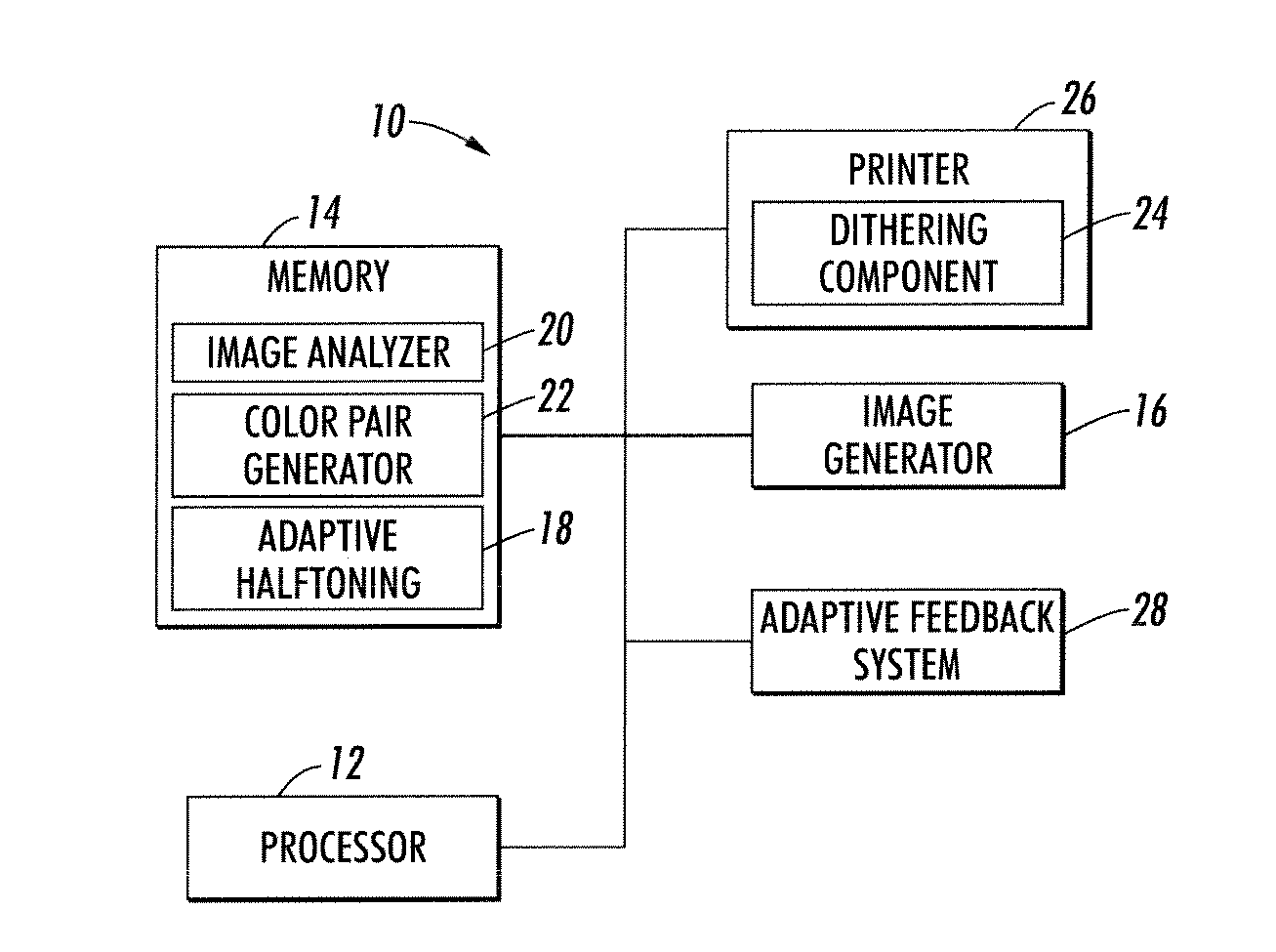
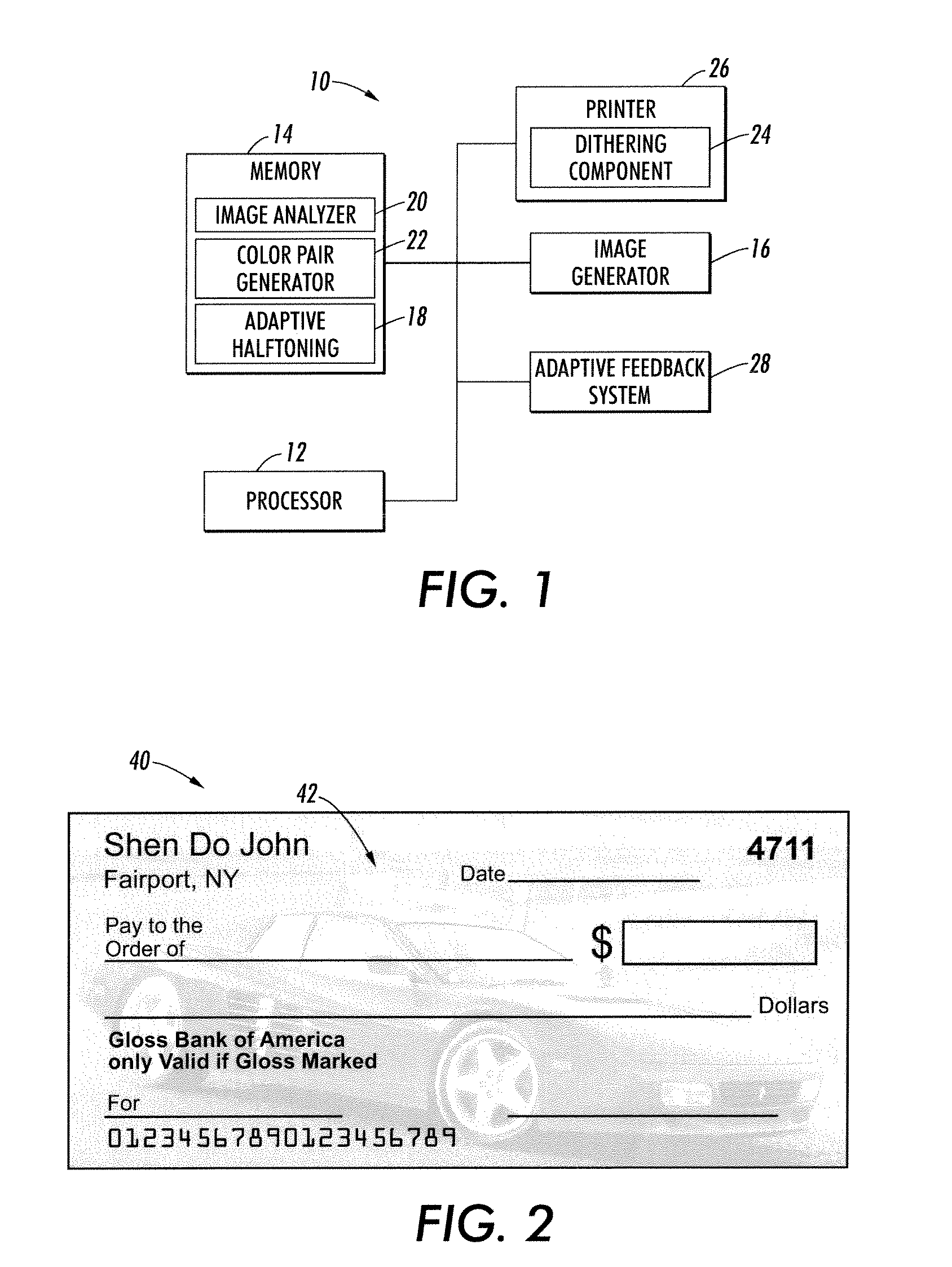
[0030]With reference to FIG. 1, an anti-counterfeit printing system 10 includes a processor 12 that executes, and a memory 14 that stores, machine-executable instructions for performing the various acts and / or functions described herein to generate UV-fluorescence encoded background images on documents (e.g., currency, personal checks, or any other type of document for which authentication is desirable). An image generator 16 generates a continuous-tone background image for printing on a document (e.g., a check, a ticket, currency, or some other suitable document). This continuous-tone background image is rendered using a set of available...
PUM
Abstract
Systems and methods are described that facilitate generating a background image with a UV-fluorescent watermark for printing on a document. A binary watermark mask is generated to separate the background image into the UV-active and the UV-dull regions. Based on the assigned binary value of the watermark mask, each pixel is assigned a UV-active or UV-dull color using an adaptive halftoning technique, in order to generate a binary UV-active image and a binary UV-dull image. A binary watermarked background image is generated by combining the binary UV-active and UV-dull images, and is printed on a document. The UV-active and UV-dull colors have different UV intensities under UV light, but are indistinguishable under normal lighting conditions. In this manner, the background image is visible when exposed to visible light, and the UV-fluorescent watermark is visible when exposed to UV light.
Description
CROSS REFERENCE TO RELATED APPLICATIONS[0001]Cross-reference is made to the following patents and applications, the entireties of which are herein incorporated by reference.[0002]U.S. Publication No. US 2007 / 0264476 A1, published Nov. 15, 2007, entitled “SUBSTRATE FLUORESCENCE MASK FOR EMBEDDING INFORMATION IN PRINTED DOCUMENTS,” by Bala et al.;[0003]U.S. Publication No. US 2007 / 0262579 A1, published Nov. 15, 2007, entitled “SUBSTRATE FLUORESCENCE PATTERN MASK FOR EMBEDDING INFORMATION IN PRINTED DOCUMENTS,” by Bala et al.;[0004]U.S. Publication No. US 2008 / 0199785 A1, published Aug. 21, 2008, entitled “SUBSTRATE FLUORESCENCE MASK UTILIZING A MULTIPLE COLOR OVERLAY FOR EMBEDDING INFORMATION IN PRINTED DOCUMENTS,” by Bala et al.;[0005]U.S. Pat. No. 5,070,413, issued Dec. 3, 1991, entitled “COLOR DIGITAL HALFTONING WITH VECTOR ERROR DIFFUSION,” by Sullivan et al.;[0006]U.S. Pat. No. 5,621,546, issued Apr. 15, 1997, entitled “METHOD AND APPARATUS FOR VECTOR ERROR DIFFUSION WITH OUTPUT ...
Claims
Application Information
Patent Timeline
Application Date:The date an application was filed.
Publication Date:The date a patent or application was officially published.
First Publication Date:The earliest publication date of a patent with the same application number.
Issue Date:Publication date of the patent grant document.
PCT Entry Date:The Entry date of PCT National Phase.
Estimated Expiry Date:The statutory expiry date of a patent right according to the Patent Law, and it is the longest term of protection that the patent right can achieve without the termination of the patent right due to other reasons(Term extension factor has been taken into account ).
Invalid Date:Actual expiry date is based on effective date or publication date of legal transaction data of invalid patent.
Patent Type & Authority Applications(United States)