Load distribution apparatus, load distribution method, and storage medium

a technology of load distribution and load distribution method, applied in the field of load distribution, can solve problems such as power saving in the information processing system

Inactive Publication Date: 2010-07-22
FUJITSU LTD
View PDF3 Cites 28 Cited by
  • Summary
  • Abstract
  • Description
  • Claims
  • Application Information

AI Technical Summary

Benefits of technology

[0009]According to an embodiment, a load distribution apparatus includes: a control unit that refers to a load information storage unit that stores load values of a plurality of information processing apparatuses, selects an information processing apparatus with the load value smaller than a predetermined threshold from the plurality of information processing apparatuses, and d

Problems solved by technology

Power saving is an issue in the

Method used


Image

  • Load distribution apparatus, load distribution method, and storage medium
  • Load distribution apparatus, load distribution method, and storage medium
  • Load distribution apparatus, load distribution method, and storage medium

Examples


first embodiment

[0045]A first embodiment will now be described in detail with reference to the drawings.

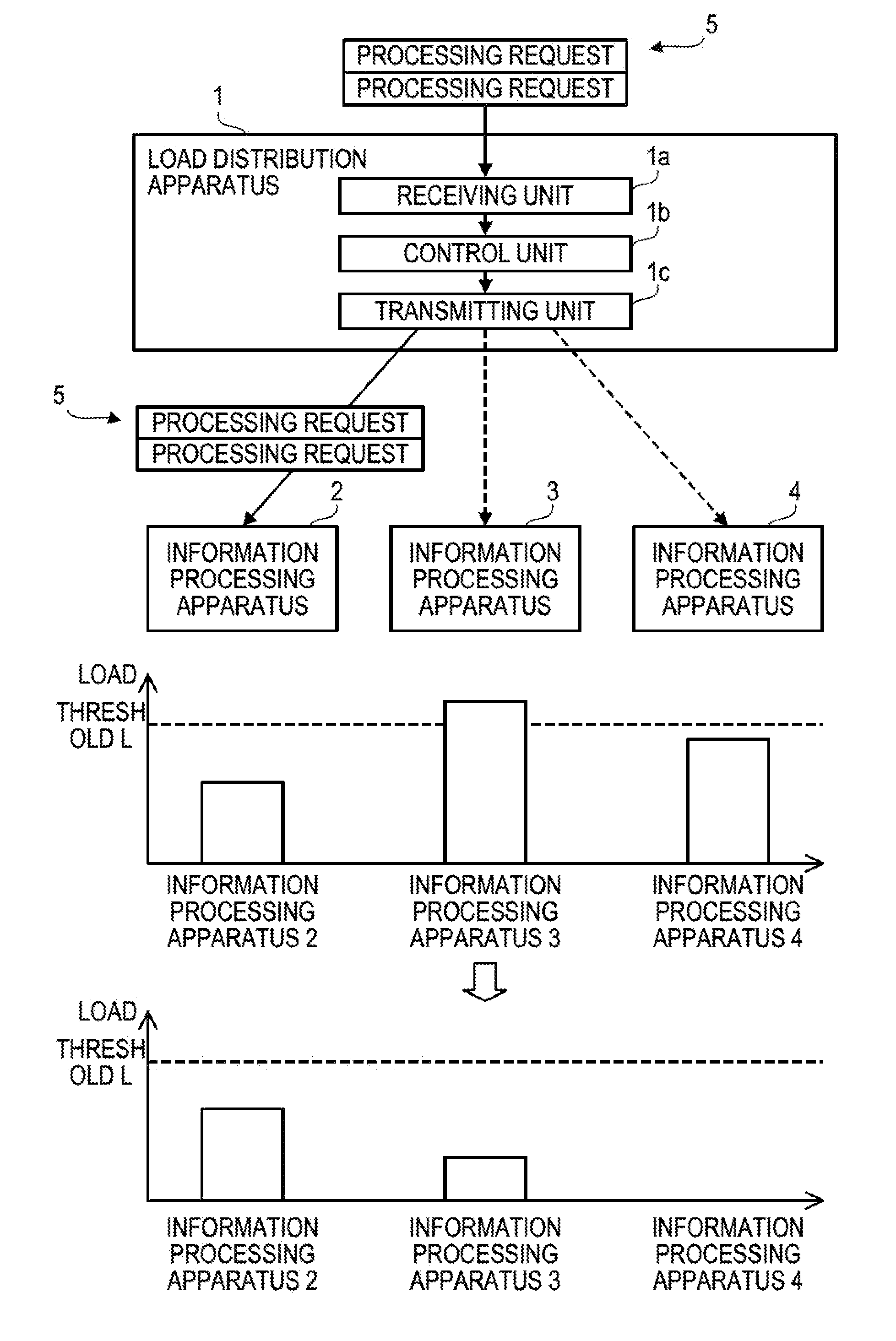
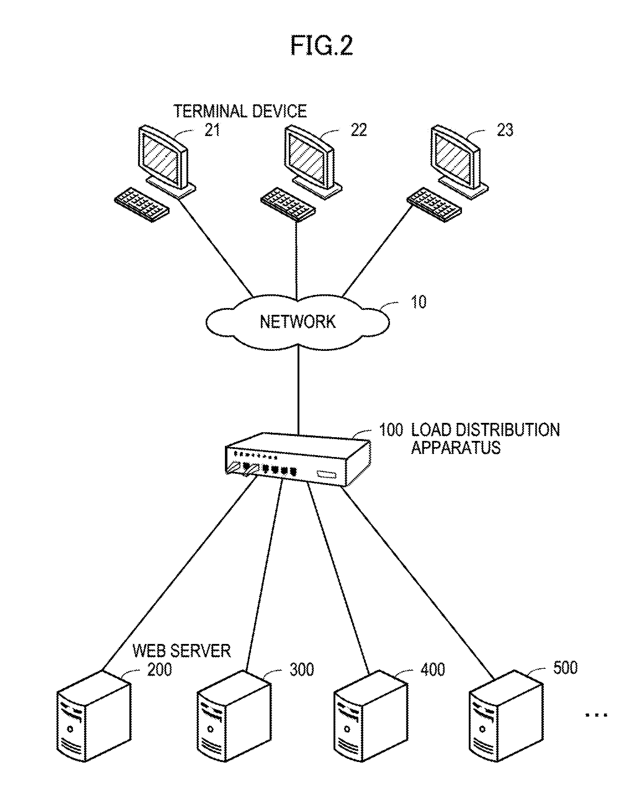
[0046]FIG. 2 illustrates a configuration of a Web system. The Web system includes a load distribution apparatus 100 and Web servers 200, 300, 400, 500, . . . . The load distribution apparatus 100 is connected to terminal devices 21, 22, and 23 through a network 10. The network 10 is a communication network such as the Internet or an intranet.

[0047]The load distribution apparatus 100 receives HTTP requests (hereinafter, simply “requests”), which are processing requests for the Web servers 200, 300, 400, 500, . . . , from the terminal devices 21, 22, and 23. The load distribution apparatus 100 determines an allocation destination of requests from among the Web servers 200, 300, 400, 500, . . . and transmits the requests to the determined Web server.

[0048]The load distribution apparatus 100 receives HTTP responses (hereinafter, simply “responses”) for the transmitted requests from the Web servers 20...

second embodiment

[0183]A second embodiment will now be described in detail with reference to the drawings. Differences from the first embodiment will be mainly described, and the description of similar items will be omitted.

[0184]The second embodiment is different from the first embodiment in that the load distribution apparatus determines the allocation destination of the requests based on the times required for the processes that the servers may execute according to the allocated requests. In the first embodiment, the allocation destination is determined based on the number of incomplete requests in the servers or the order of allocation of processes. Meanwhile, in the second embodiment, the loads of the servers are appropriately figured out even if the processing times of the requests are different.

[0185]A load distribution system according to the second embodiment may be realized by a system configuration equivalent to the load distribution system according to the first embodiment illustrated in...


PUM


Abstract

A load distribution apparatus includes: a control unit that refers to a load information storage unit that stores load values of a plurality of information processing apparatuses, selects an information processing apparatus with the load value smaller than a predetermined threshold from the plurality of information processing apparatuses, and determines the information processing apparatus with the load value smaller than a predetermined threshold as an allocation destination of processing requests until the load value of the information processing apparatus reaches the predetermined threshold; and a transmitting unit that transmits the processing requests to the allocation destination determined by the control unit.

Description

[0001]This application is based upon and claims the benefit of priority from the prior Japanese Patent Application No. 2009-7143 filed on Jan. 16, 2009, the entire contents of which are incorporated herein by reference.[0002]1. Field[0003]The embodiments discussed herein are related to load distribution for allocating processing requests to a plurality of information processing apparatuses.[0004]2. Description of Related Art[0005]Conventionally, a load distribution system is used in which a plurality of servers that provide the same services are arranged, and processing requests are allocated and distributed to the plurality of servers. The load distribution system includes a load distribution apparatus. In the load distribution apparatus, a plurality of servers receive processing requests at front stages, and the processing requests are allocated to the servers so that the load of the servers is uniform.[0006]Examples of a load distribution method of the load distribution apparatus...

Claims


Application Information

Patent Timeline
IPC IPC(8): G06F15/173G06F9/46G06F1/32
CPCG06F1/3203G06F9/505Y02D10/22G06F2209/5022G06F9/5094Y02D10/00
Inventor SANO, TAKESHISASAKI, KAZUO
Owner FUJITSU LTD
Why Eureka
Try Eureka