Liquid containers

Active Publication Date: 2010-09-16
BROTHER KOGYO KK
View PDF6 Cites 21 Cited by
  • Summary
  • Abstract
  • Description
  • Claims
  • Application Information

AI Technical Summary

Benefits of technology

[0012]According to an embodiment of the present invention, a liquid container comprises a case and a liquid chamber formed in the case. The liquid chamber is configured to store liquid therein. The liquid container further comprises a liquid supply portion configured to supply the liquid from the liquid chamber to an exterior of the case, and an air introduction portion configured to introduce air from the exterior of the case into the liquid chamber. The air introduction portion comprises an air communication passage formed in the case. The liquid chamber is configured to be in fluid communication with the exterior of the case through the air communication passage. The air communication passage has an air communication end, and extends from the air communication end to the liquid chamber, wherein the air communication end is op

Problems solved by technology

Therefore, if the inkjet recording apparatus is moved, ink may leak to the exterior of the ink cartridge via the air introduction portion.
For example, if the inkjet recording apparatus is broken and the inkjet recording apparatus is sent for repair to its manufacturer with the ink cartridge mounted on the inkjet recording apparatus, the inkjet recording apparatus may be shaken hard or turned upside down during transportation.
This

Method used


Image

  • Liquid containers
  • Liquid containers
  • Liquid containers

Examples


Embodiment Construction

[0023]Embodiments of the present invention, and their features and advantages, may be understood by referring to FIGS. 1-8, like numerals being used for like corresponding parts in the various drawings.

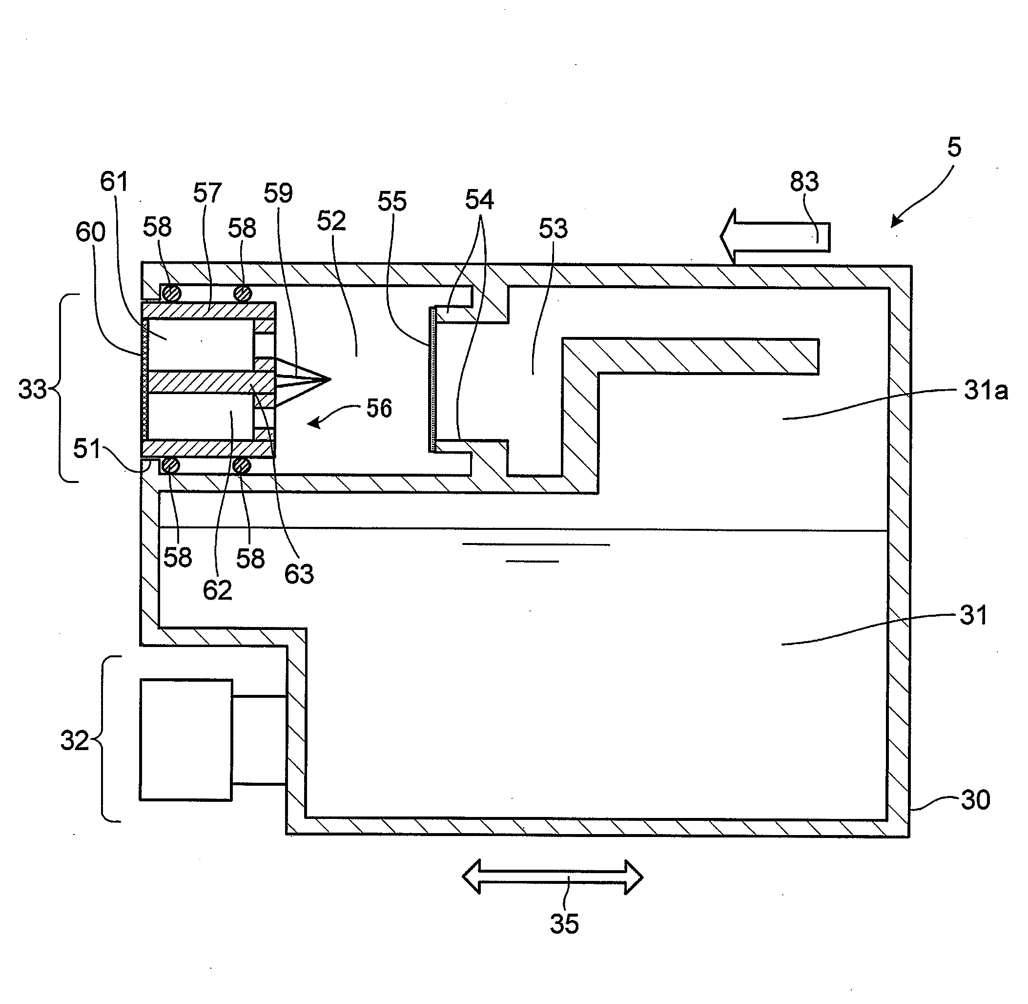
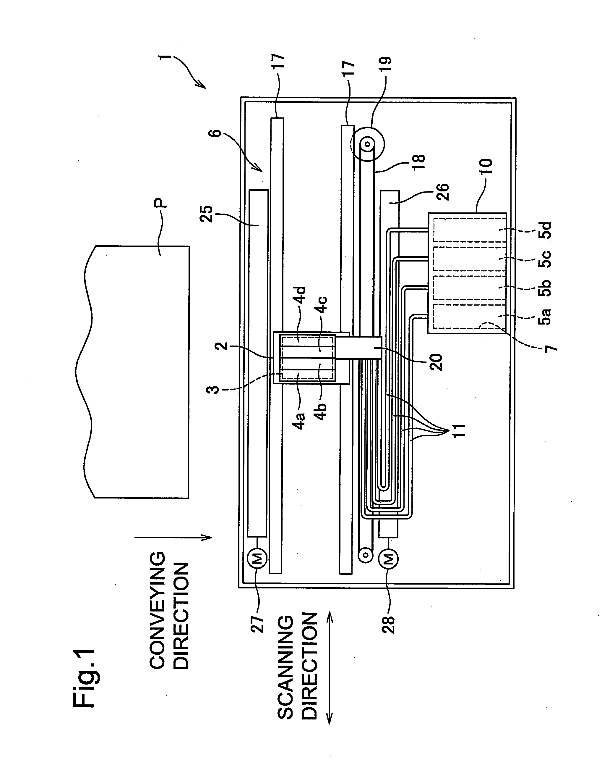
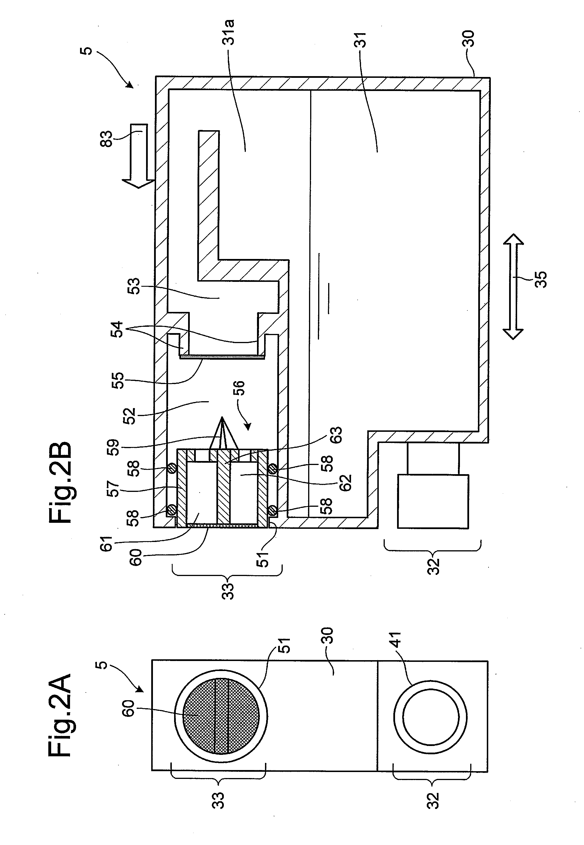
[0024]Referring to FIG. 1, a liquid container, e.g., an ink cartridge 5, according to an embodiment of the present invention, may be mounted to a printer 1. Printer 1 may comprise a carriage 2 configured to reciprocate in a scanning direction, e.g., the right-left direction in FIG. 1, an inkjet head 3 and four sub-tanks 4a-4d mounted on carriage 2, a holder 10 configured to mount thereon four ink cartridges 5a-5d, and a conveying mechanism 6 configured to convey a recording sheet P in a conveying direction indicated in FIG. 1.

[0025]Carriage 2 may be configured to reciprocate along two guide shafts 17. Each shaft 17 may extend parallel to the scanning direction. An endless belt 18 may be coupled to carriage 2. A carriage drive motor 19 may be configured to drive endless belt 18. Carria...


PUM


Abstract

A liquid container includes an air introduction portion configured to introduce air into a liquid chamber. The air introduction portion includes an air communication passage, and a blocking member positioned in the air communication passage and configured to block the air communication passage. The air introduction portion also includes a movable member positioned in the air communication passage and configured to move toward the blocking member, such that blockage of the air communication passage by the blocking member is released. The movable member includes an air passage formed therethrough, and the air passage is in fluid communication with the air communication passage. The air introduction portion further includes a gas-permeable film positioned on the movable member and closing the air passage.

Description

CROSS REFERENCE TO RELATED APPLICATION[0001]The present application claims priority to and the benefit of Japanese Patent Application No. 2009-062415, which was filed on Mar. 16, 2009, the disclosure of which is incorporated herein by reference in its entirety.BACKGROUND OF THE INVENTION[0002]1. Field of the Invention[0003]The present invention relates to liquid containers comprising an air introduction portion configured to introduce air into a liquid chamber.[0004]2. Description of Related Art[0005]Japanese Laid-Open Patent Publication No. 2005-153285 or its corresponding U.S. Patent Application Publication No. 2005 / 0134663 A1 describes an ink cartridge for use in an inkjet recording apparatus. The ink cartridge includes an ink supply portion, through which ink contained in an ink chamber is supplied to the inkjet recording apparatus. The ink cartridge further includes an air introduction portion configured to introduce air into the ink chamber. A valve is positioned in the air in...

Claims


Application Information

Patent Timeline
IPC IPC(8): B41J2/19
CPCB41J2/17509B41J2/17523B41J2/1752B41J2/17513
Inventor KANBE, TOMOHIRO
Owner BROTHER KOGYO KK
Why Eureka
Try Eureka