Centrifugation systems with non-contact seal assemblies

a technology of non-contact sealing and centrifugation system, which is applied in the direction of centrifuges, rotary centrifuges, etc., can solve problems such as premature failure, and achieve the effect of mitigating fluid leakag

Active Publication Date: 2015-07-23
ALFA WASSERMANN INC
View PDF1 Cites 8 Cited by
  • Summary
  • Abstract
  • Description
  • Claims
  • Application Information

AI Technical Summary

Benefits of technology

[0009]A centrifugation system is provided that has a non-contact seal assembly to mitigate leakage of fluids.
[0013]A centrifugation system is provided that includes a drive assembly, a non-contact seal assembly, and a tank assembly. The drive assembly has an upper housing and a lower housing separated by a top bearing plate with a rotor opening defined therein. The lower housing has a drive disposed therein with a rotor shaft aligned with the rotor opening. The non-contact seal assembly has an upper guard and a skirted pivot. The non-contact seal assembly is secured to the top bearing plate at the rotor opening so that the skirted pivot is operatively coupled to the rotor shaft for rotation without contacting the upper guard with the upper guard and the skirted pivot forming a labyrinth seal to mitigate leakage of fluid from the upper housing through the rotor opening into the drive in the lower housing. The tank assembly has a centrifuge rotor rotatably housed therein. The tank assembly is connectable to the lower housing so that the centrifuge rotor is rotatably driven by the drive via the skirted pivot.
[0024]In other embodiments alone or in combination with one or more of the aforementioned or aftmetioned embodiments, the centrifugation system can further include one or more features on seal surfaces of the upper guard and / or skirted pivot. The one or more features forming fluid vortices within the non-contact seal assembly sufficient to mitigate leakage of the fluid from the upper housing through the rotor opening into the drive in the lower housing.
[0026]In other embodiments alone or in combination with one or more of the aforementioned or aftmetioned embodiments, the gas flow is sufficient to overcome any vortices and / or pressure differentials generated by the rotation of the skirted pivot.
[0032]In other embodiments alone or in combination with one or more of the aforementioned or aftmetioned embodiments, the gas flow is sufficient to overcome any vortices and / or pressure differentials generated by the rotation of the skirted pivot.

Problems solved by technology

It has been determined by the present disclosure that some prior art centrifugation systems can experience undesired leakage of fluids into the electric motor, hydraulic drive, or pneumatic drive, causing premature failure.

Method used


Image

  • Centrifugation systems with non-contact seal assemblies
  • Centrifugation systems with non-contact seal assemblies
  • Centrifugation systems with non-contact seal assemblies

Examples


Embodiment Construction

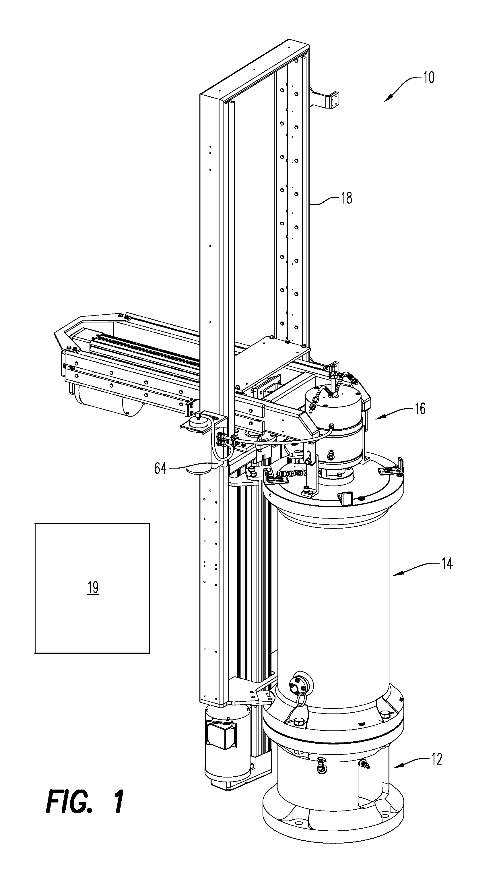
[0060]Referring to the drawings and in particular to FIG. 1, an exemplary embodiment of a centrifugation system according to the present disclosure is shown and is generally referred to by reference numeral 10.

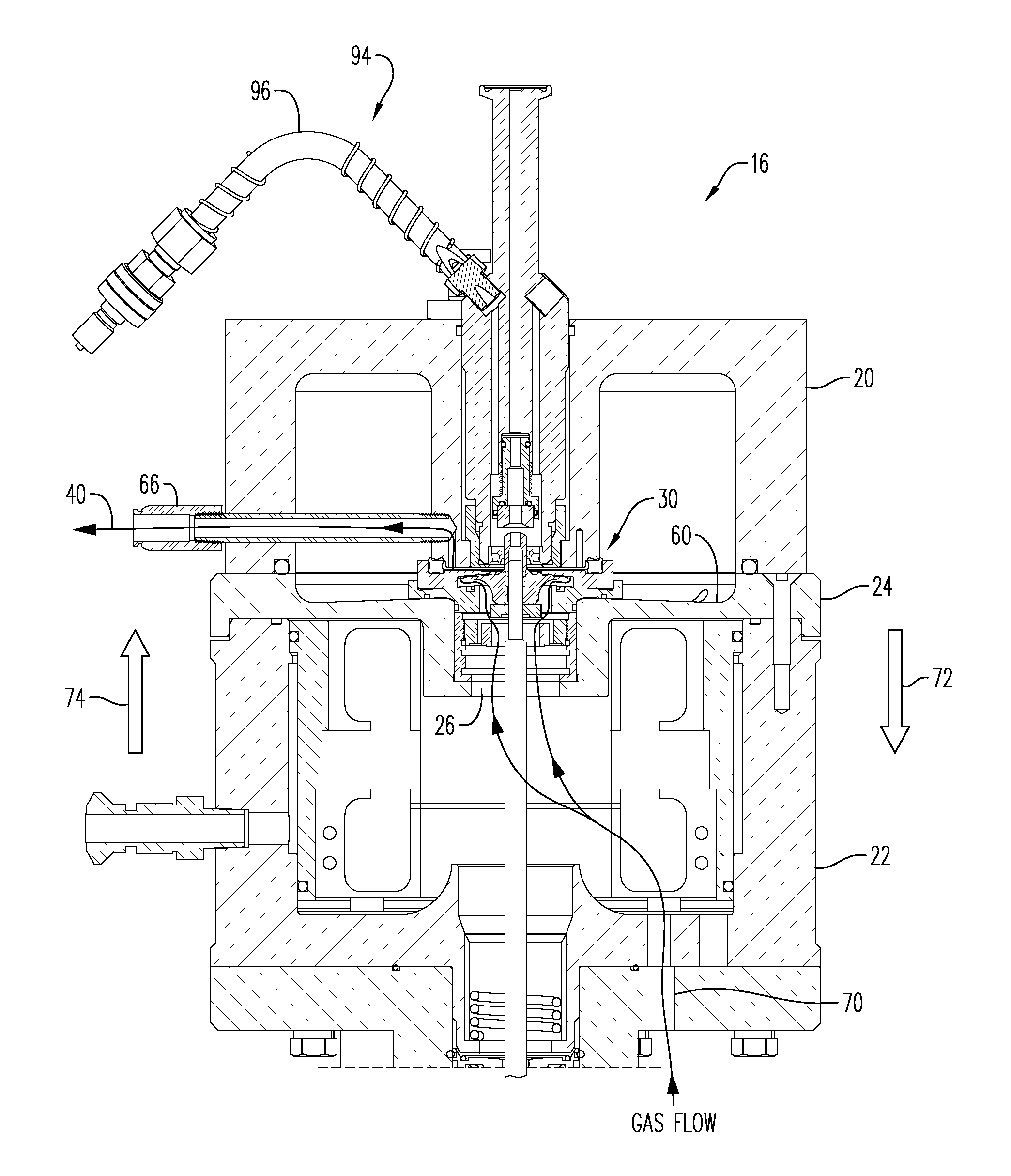
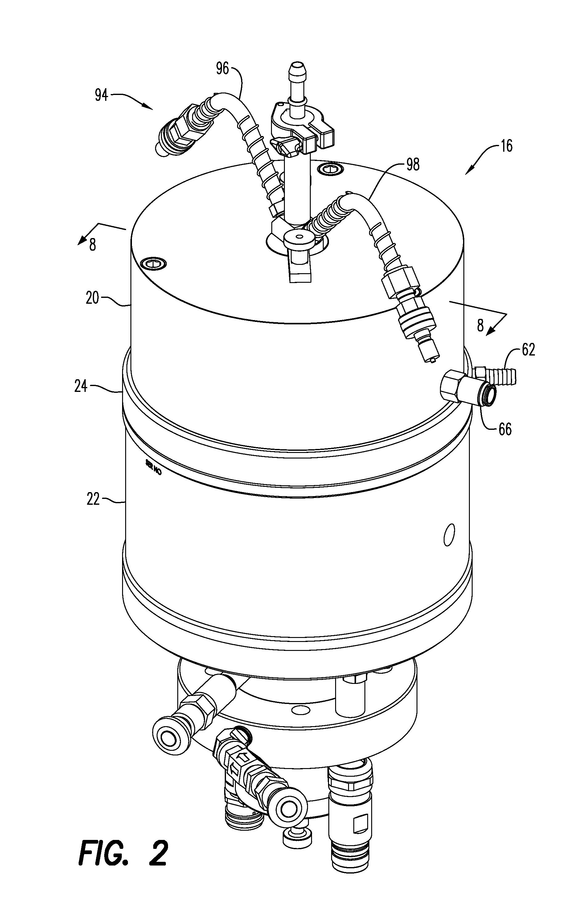
[0061]Centrifugation system 10 (hereinafter “system”) includes a base or stand 12, a centrifugation tank assembly 14, a drive assembly 16, and a lift assembly 18. In some embodiments, system 10 can also include a control interface 19 in electrical communication (e.g., wired, wireless, or combinations thereof) with, for example, drive assembly 16, lift assembly 18, and other components of the system described herein to allow the operator to control the various movements and operations of the system. Control interface 19 can be any human-machine-interface (HMI) such as, but not limited to, a touch screen that allows the operator to control the various components of system 10.

[0062]Advantageously, system 10 includes a non-contact seal assembly configured to mitigate leakage of fl...


PUM


Abstract

Centrifugation systems are provided that have a non-contact seal assemblies including an upper guard and a skirted pivot, as well as a pressure source that provides a gas flow between the upper guard and a surface of the skirted pivot. In some embodiments, the non-contact seal assembly further includes a lower guard having one or more capillary channels defined on an upper surface.

Description

CROSS REFERENCE TO RELATED APPLICATIONS[0001]This application claims the benefit of U.S. Provisional Application Ser. No. 61 / 930,173 filed Jan. 22, 2014 the contents of which are incorporated by reference herein.BACKGROUND OF THE INVENTION[0002]1. Field of the Invention[0003]The present disclosure is related to centrifugation systems. More particularly, the present disclosure is related to centrifugation systems with improved non-contact seal assemblies.[0004]2. Description of Related Art[0005]Centrifugal separation is commonly used to separate a solution into its constituent parts based on the density of the constituents. Here, the centrifugation system creates a centrifugal force field by spinning the solution containing the constituents to be separated, thus causing the constituents of higher density to separate from the solution.[0006]Many different styles of centrifugation systems have been used and are typically classified by, among other things, the flow in the system (e.g., ...

Claims


Application Information

Patent Timeline
Patent Type & Authority Applications(United States)
IPC IPC(8): B04B15/00B04B9/06B04B9/02B04B15/02
CPCB04B15/00B04B9/02B04B9/06B04B15/02B04B9/00B04B9/04B04B9/12
Inventor SPIEGEL, KURT MICHAELWEILAND, ERIC BERNARD
Owner ALFA WASSERMANN INC
Why Eureka
Try Eureka