Machine and integrated hybrid drive with regenerative hydraulic force assist

Inactive Publication Date: 2008-08-28
GEIGER INNOVATIVE TECH
View PDF3 Cites 11 Cited by
  • Summary
  • Abstract
  • Description
  • Claims
  • Application Information

AI Technical Summary

Benefits of technology

[0013]The present invention is an energy efficient mechanical-hydraulic machine with an integrated hybrid drive and a regenerative hydraulic force assist. The inventio

Problems solved by technology

Other shared aspects are high investments, high operating costs, pollution, noise and frequent service.
Vertical mechanical presses are popular because they rapidly move rams and pallets while hydraulic presses are slower and consume more energy.
However, mechanical stamping presses are large, heavy, noisy, expensive to operate and require frequent service.
However, hydraulic driven presses have lower numbers of cycles per time, are generally complex (requ

Method used


Image

  • Machine and integrated hybrid drive with regenerative hydraulic force assist
  • Machine and integrated hybrid drive with regenerative hydraulic force assist
  • Machine and integrated hybrid drive with regenerative hydraulic force assist

Examples


first embodiment (fig.1)

First Embodiment (FIG. 1)

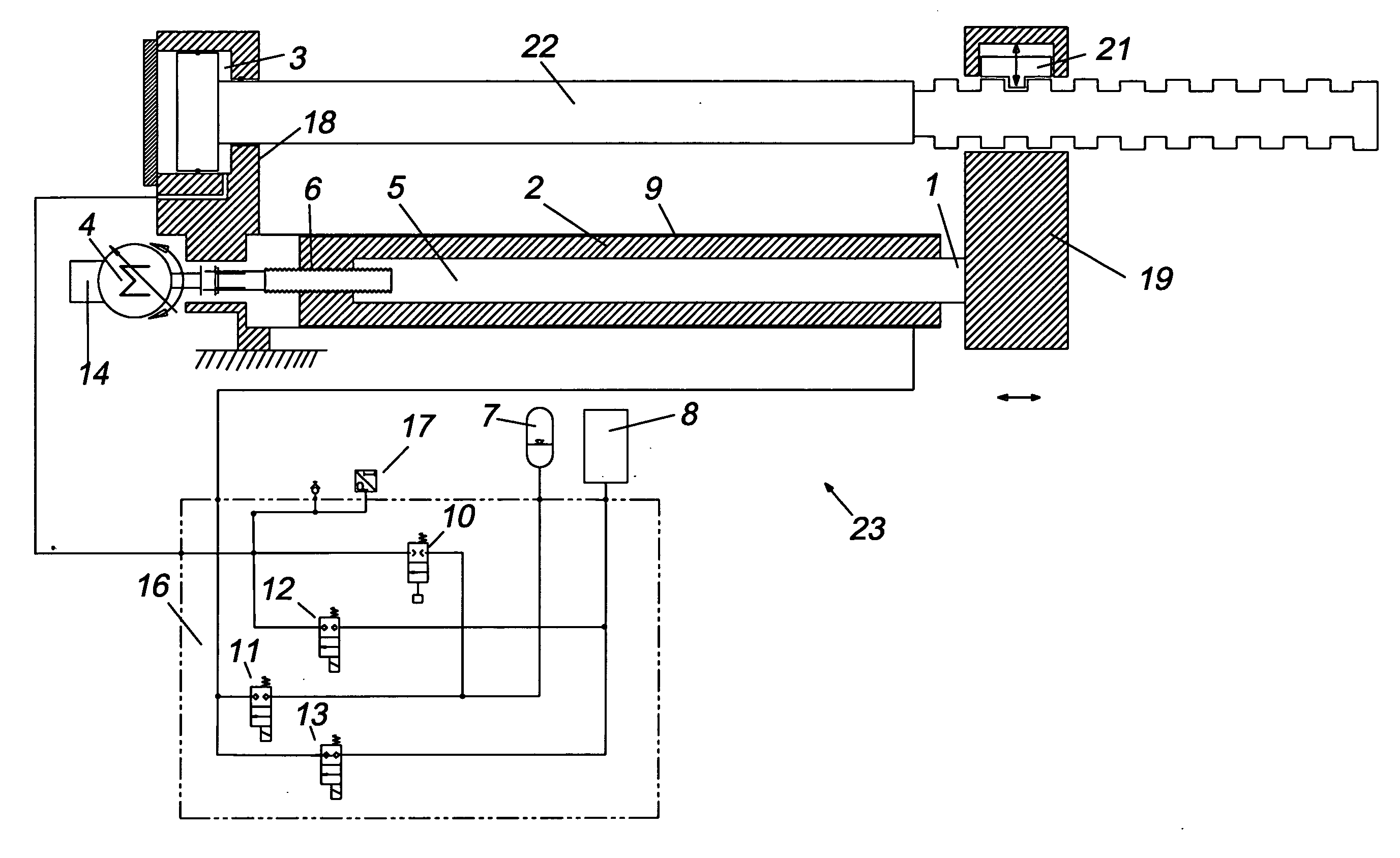
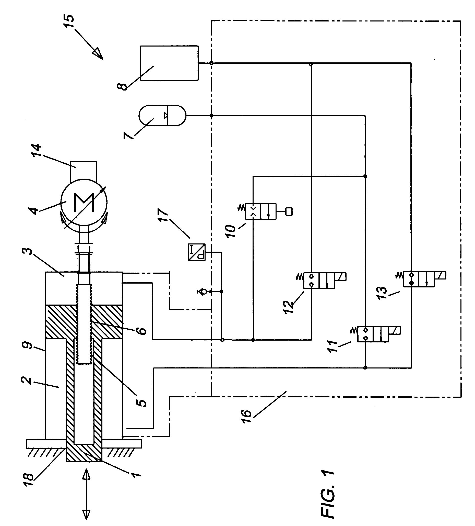
[0030]Referring now to the drawings wherein like numerals designate like and corresponding parts throughout the several views, in FIG. 1 a hybrid machine drive 15 is shown according to the present invention.

[0031]As used in the description, the term “hybrid drive” refers to a mechanical-hydraulic drive for sequentially displacing an output member of a single, dual and multiple action machine in three stages; i.e., a high speed low force first stage, followed by a low speed high force stage in the same direction as the first stage, followed by a high speed low force stage in a second direction which is opposite to the first stage. The term “action” refers to an action of a machine such as a “stamping press” or an action of a machine output member such as a ram of a “stamping press”. The terms “horizontal”, “rightward”“upward”, “rightwardly”, “leftwardly”, “downward” and “downwardly” refer to orientations in a particular drawing figure that faces the reader. S...

second embodiment (fig.2)

Second Embodiment (FIG. 2)

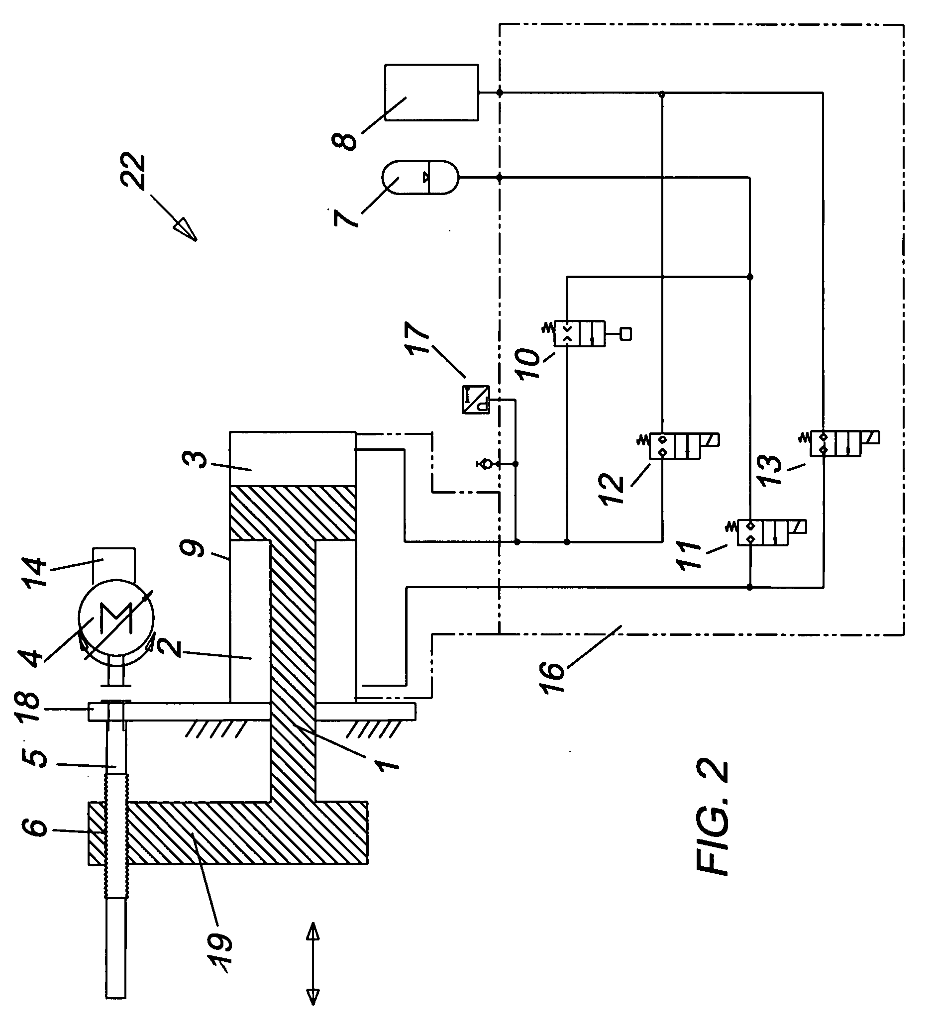
[0037]Referring now to FIG. 2, a hybrid drive 22 is shown which is similar to the first embodiment, except that the ball screw and nut (mechanical) drive portion is external to the hydraulic cylinder 9, accumulator 7 and fluid reservoir 8 (hydraulic) drive portion. The ball screw and nut drive (shaft 5 and nut 6) is integrated into a moving platen 19 instead of output member 1.

[0038]The hybrid drive 22 is also shown as having an accumulator 7 that is operatively arranged to displace the output member 1.

third embodiment (fig.4)

Third Embodiment (FIG. 4)

[0039]Referring now to the drawing FIG. 4, a vertical three platen press (which could be a horizontal press) is shown based on the hybrid drive 15 of FIG. 1. The hybrid three platen press, however, could be horizontal instead of vertical. The hybrid drive 15 is fixed to an upper stationary platen 31. The hybrid drive's output member is fixed a moving platen 33 and an upper die / mold half 34 is fixed to the moving platen. The high-speed low force and low-speed high force displacements are upward and downward. The hybrid drive's output member, moving platen 33 and upper die / mold half 34 are accelerated downwardly by gravitational and drive forces. A lower fixed platen 36 and attached die / mold half 35 are attached to the fixed upper platen by tie rods 32 and nuts 30.


PUM


Abstract

A mechanical-hydraulic machine and an integrated hybrid drive with a regenerative force assist for eliminating pumps and intensifiers and reducing the energy consumption, operating costs, investment costs, weight and size of machines and improving their performance. The integrated hybrid drive is comprised of common mechanical and hydraulic components. The regenerative hydraulic force assist converts gravitational and deceleration forces of the machine into fluid pressure, stores the fluid pressure and applies the fluid pressure to clamping of dies or molds and/or performing machine operations. A closed loop control system controls the flow of fluid between the hydraulic drive and regenerative force assist.

Description

FIELD OF THE INVENTION[0001]This invention relates to machines and more particularly to a mechanical-hydraulic machine and an integrated hybrid drive with a regenerative force assist.BACKGROUND OF THE INVENTION[0002]Large machines, such as stamping presses, die casting machines, extrusion presses, powder metal compacting machines and injection molding machines share certain aspects. One shared aspect is that members, such as pallets and rams open and close dies or molds and / or perform operations, such as clamping, stamping, extruding, powder metal compacting, and the like. Another aspect is that high forces clamp and perform stamping, forging, machining, metal powder compacting operations. Other shared aspects are high investments, high operating costs, pollution, noise and frequent service.[0003]Machines are divided in accordance with their drives. The drives, also called actuators, clamp and perform other operations. They are mainly mechanical and hydraulic. The type of drive dete...

Claims


Application Information

Patent Timeline
IPC IPC(8): B60T17/22
CPCB60T1/10Y10T74/173B30B1/32B30B1/18
Inventor GEIGER, DAVID
Owner GEIGER INNOVATIVE TECH
Why Eureka
Try Eureka