Finned tube for heat exchangers, heat exchanger, apparatus for fabricating heat exchanger finned tube and process for fabricating heat exchanger finned tube

a technology of heat exchanger and finned tube, which is applied in the field of finned tube for heat exchanger, heat exchanger, apparatus process for fabricating heat exchanger finned tube, can solve the problems of requiring cumbersome work, reducing heat exchange efficiency, and requiring high material cost, so as to achieve low cost, increase cost, and simple construction

Inactive Publication Date: 2006-03-23
SHOWA DENKO KK
View PDF3 Cites 10 Cited by
  • Summary
  • Abstract
  • Description
  • Claims
  • Application Information

AI Technical Summary

Benefits of technology

[0024] The production apparatus of the present invention has a relatively simple construction and is nevertheless capable of producing a heat exchanger finned tube. The tube clamp upper and lower plates act to clamp the straight tube portion of the fin fixing tube to be enlarged with a fluid, preventing the tube from rupturing during enlargement. Moreover, the apparatus is low in cost. The straight tube portion of the fin fixing tube can be prevented from rupturing while being enlarged with use of the fluid, by restraining the finless part with a restraining die approximately over the entire length thereof, but the apparatus then becomes costly. The finless part of the heat exchanger finned tube may differ in length with the type of heat exchanger, and production of finned tubes having finless parts of varying lengths necessitates preparation of restraining dies specifically for the respective finless parts of different lengths to result in increases in cost. With the production apparatus of the present invention, on the other hand, the tube to be enlarged can be prevented from rupturing merely by varying the number of tube clamp lower plates to be arranged in the fin setting clearances of the fin setting jig and the number of upper plates to be arranged on the lower plates even when the heat exchanger finned tube to be produced has a finless part of altered length. Accordingly upper and lower plates need only to be prepared in an increased number. This results in a lower cost than when various metal members must be prepared for specific use.
[0025] In the heat exchanger finned tube production apparatus of the invention, each of the fin support plates may have two cutouts formed as spaced apart in the upper edge thereof for two straight tube portions of a fin fixing hairpin tube to fit in, and each pair of corresponding tube clamp upper and lower plates may have two through holes formed therebetween for inserting the two straight tube portions of the fin fixing tube therethrough, the through holes having the same pitch as the two cutouts. In this case, the heat exchanger finned tube wherein the fin fixing tube is in the form of a hairpin as described above can be produced at a low cost without permitting the rupture of the straight tube portions of the tube.

Problems solved by technology

However, the conventional heat exchanger has the problem of requiring a high material cost and having great weight in its entirety since the outer pipes and the inner pipe must be used.
The heat exchanger has another problem in that the insertion of the straight pipe portions of the inner pipe into the outer pipes requires cumbersome work.
This entails the problem of impaired intimate contact between the pipe portion and the outer pipe to result in a lower heat transfer efficiency and a lower heat exchange efficiency.
The heat exchanger therefore has the problem that the adhesive or compound is cumbersome to apply.
However, this heat exchanger has the problem that the hairpin tube ruptures at a finless portion thereof which has no fins when the tube is enlarged with the pressure fluid.

Method used


Image

  • Finned tube for heat exchangers, heat exchanger, apparatus for fabricating heat exchanger finned tube and process for fabricating heat exchanger finned tube
  • Finned tube for heat exchangers, heat exchanger, apparatus for fabricating heat exchanger finned tube and process for fabricating heat exchanger finned tube
  • Finned tube for heat exchangers, heat exchanger, apparatus for fabricating heat exchanger finned tube and process for fabricating heat exchanger finned tube

Examples


Embodiment Construction

[0044] Embodiments of the present invention will be described below with reference to the drawings. The term “aluminum” as used in the following description includes aluminum alloys in addition to pure aluminum. Further in the following description, the left-hand sides of FIG. 1 will be referred to as “front,” the right-hand side thereof as “rear,” and the upper and lower sides and left- and right-hand sides of FIGS. 2 and 6 as “upper,”“lower,”“left” and “right”, respectively.

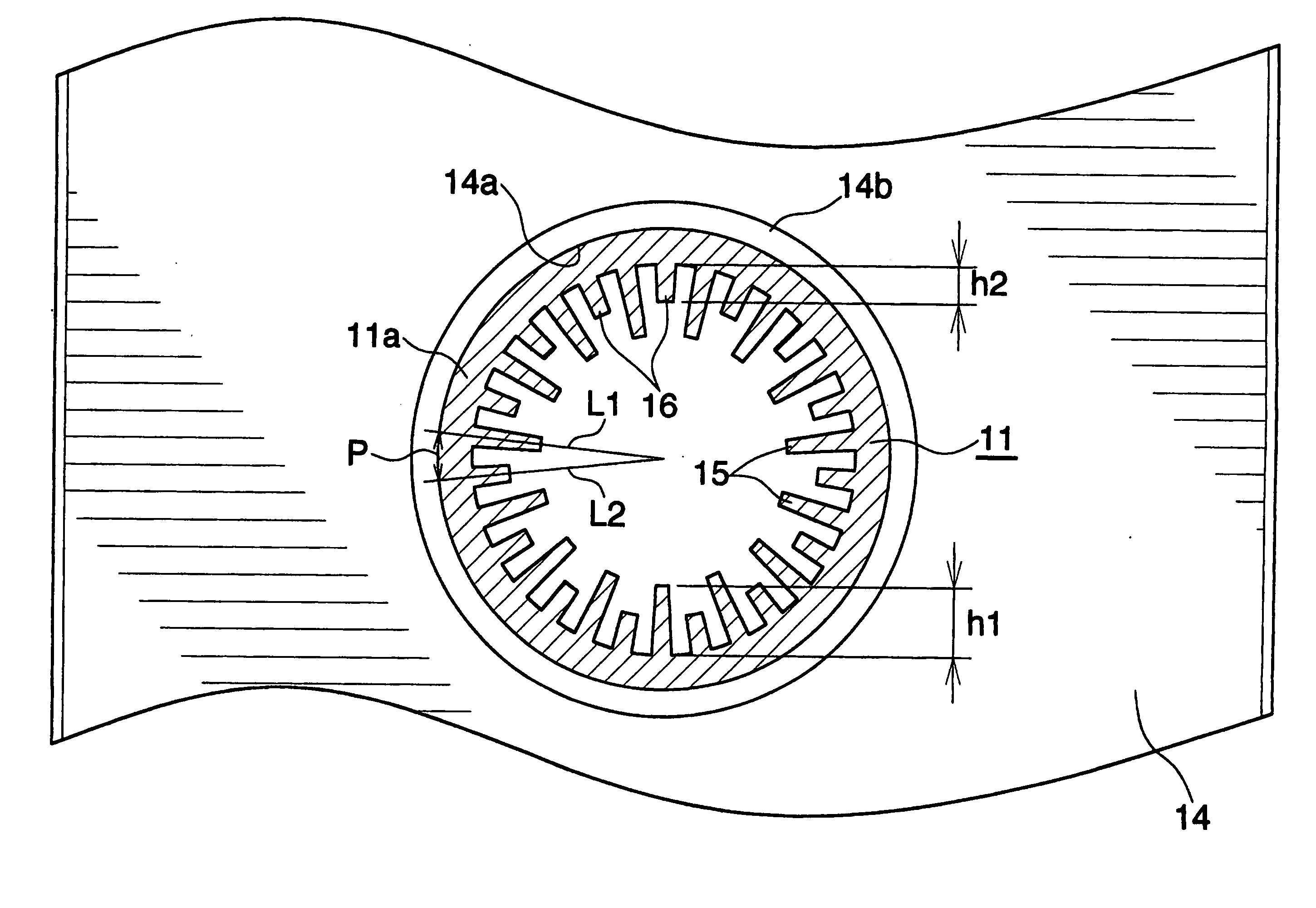
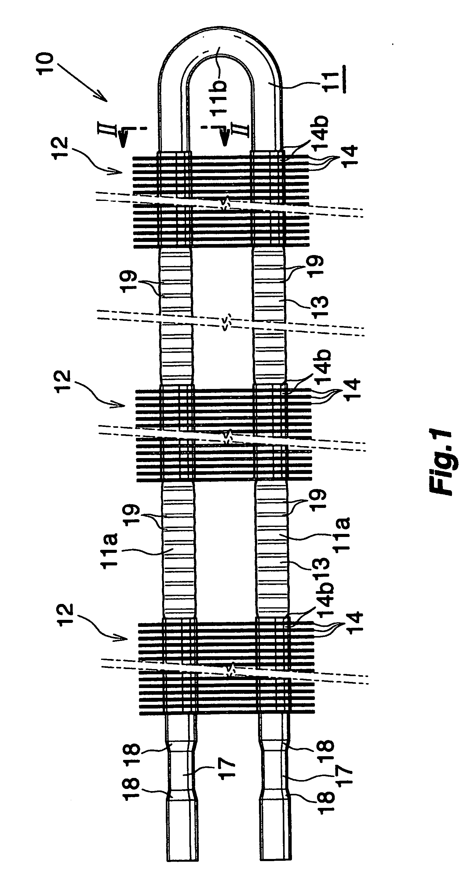
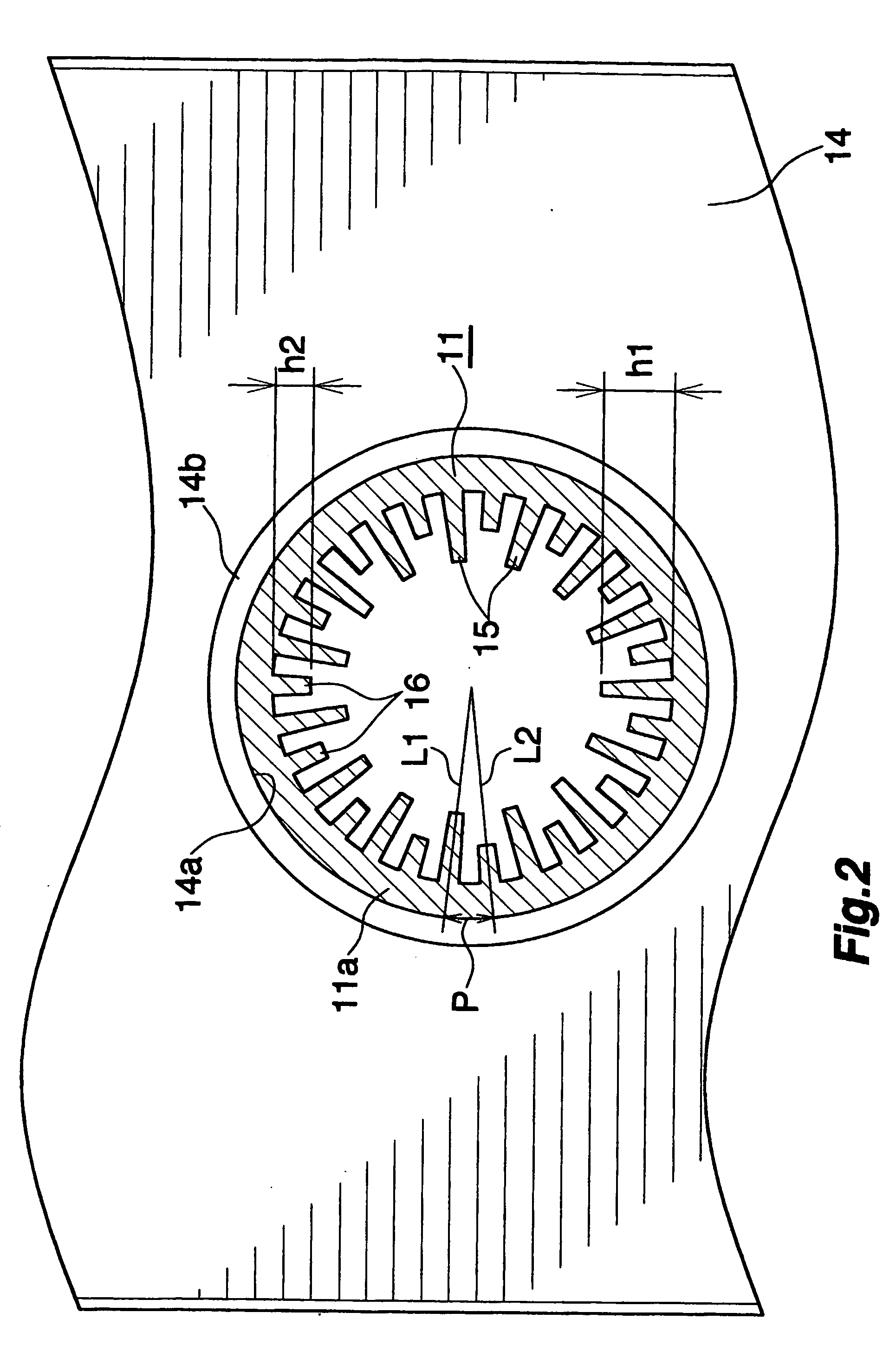
[0045] FIGS. 1 to 2 show a finned tube for use in heat exchangers, FIGS. 4 to 8 show an apparatus and a process for producing the finned tube, and FIG. 9 shows a process for fabricating a heat exchanger with the use of the finned tube. Further FIG. 10 shows the overall construction of the heat exchanger fabricated using the finned tube.

[0046] With reference to FIG. 1, a finned tube 10 for use in heat exchangers comprises a fin fixing hairpin tube 11 made of aluminum and comprising a tube having no weld seam, ...


PUM


Abstract

A plurality of fin groups 12 each comprising parallel plate fins 14 are arranged on two straight tube portions 11a of a fin fixing hairpin tube 11 longitudinally of the tube portions at a spacing, by forming two tube inserting holes 14a as spaced apart in each of the plate fins 14 and inserting the two straight tube portions 11a through the respective holes 14a of the plate fins 14. The hairpin tube 11 is enlarged with use of a fluid to fixedly fit the plate fins 14 of the fin groups 12 around the straight tube portions 11a of the tube 11. The straight tube portions 11a of the tube 11 each have a finless part 13 provided between each pair of adjacent fin groups 12. The finless part 13 of each straight tube portion 11a bears clamp marks 19 on the outer peripheral surface thereof. A heat exchanger comprising a heat exchanger finned tube 10 thus constructed is adapted to diminish leakage of the refrigerant and achieves a desired refrigeration efficiency.

Description

CROSS REFERENCE TO RELATED APPLICATIONS [0001] This application is an application-filed under 35 U.S.C. §111(a) claiming the benefit pursuant to 35 U.S.C. §119(e) (1) of the filing data of Provisional Application No. 60 / 440,373 filed Jan. 16, 2003 pursuant to 35 U.S.C. §111(b).TECHNICAL FIELD [0002] The present invention relates to heat exchanger finned tubes for use in fabricating heat exchangers useful as evaporators of refrigeration devices such as refrigerators and refrigerated showcases, heat exchangers, an apparatus for fabricating the heat exchanger finned tube and a process for fabricating the heat exchanger finned tube. BACKGROUND ART [0003] For use in refrigerators and refrigerated showcases, studies are recently under way on the replacement of chlorofluorocarbon refrigerants by hydrocarbon refrigerants which are less likely affect the depletion of the ozone layer or global warming. Since hydrocarbon refrigerants are inflammable, leakage of the refrigerant must be diminish...

Claims


Application Information

Patent Timeline
Patent Type & Authority Applications(United States)
IPC IPC(8): F25B39/02F28D1/04F28F1/42F28D7/12
CPCF25B9/002F25B39/022F28F1/40F28D1/0477F28F1/32F25B2500/01
Inventor WATANABE, ISAO
Owner SHOWA DENKO KK
Why Eureka
Try Eureka