Halation-Free Light-Emitting Diode Holder

Inactive Publication Date: 2010-11-04
HELIO OPTOELECTRONICS
View PDF3 Cites 17 Cited by
  • Summary
  • Abstract
  • Description
  • Claims
  • Application Information

AI Technical Summary

Benefits of technology

[0048]2. By the nano-material layers provided on the second surface of the die holder, the adhesion between the optical gel and the second surface is reduced, so the optical gel is prevented from climbing along the second surface under the effect of the capillarity.
[0049]3. In the specially configured die holder, the area of the first surface is greater than the area of the opened-end, so the optical gel is prevented by the gravitation from climbing, thereby eliminating a light halation around the light pattern produced by the light-emitting diode, and in turn improving the luminance uniformity of the light-emitting diode.
[0050]In brief, the present invention relates to a halation-free light-emitting diode holder, which includes a body and a retaining portion. The body includes a die holder, and the die holder has a first surface, a second surface, and an opened end. The retaining portion is provided on the sec

Problems solved by technology

However, when applied directly to the LED chip, the optical gel may have the fluorescent substance precipitated unevenly on the chip, which leads to uneven thickness of the fluorescent substance over the LED chip.
Thus, the light emitted by the LED chip passing through the optical gel activates an uneven amount of the fluorescent substance,

Method used


Image

  • Halation-Free Light-Emitting Diode Holder
  • Halation-Free Light-Emitting Diode Holder
  • Halation-Free Light-Emitting Diode Holder

Examples


Example

[0064]For further illustrating the means and functions by which the present invention achieves its objectives, the following description, to be read in conjunction with the accompanying drawings and preferred embodiments, is set forth as below to illustrate the implement, structure, features and effects of the halation-free light-emitting diode holder of the present invention.

[0065]The following preferred embodiments together with the accompanying drawings are made to clearly exhibit the above-mentioned and other technical contents, features and effects of the present invention. Through the exposition by means of the specific embodiments, people skilled in the art would further understand the technical means and effects the present invention adopts to achieve the above-indicated objectives. However, the accompanying drawings are intended for reference and illustration, but not limiting the present invention.

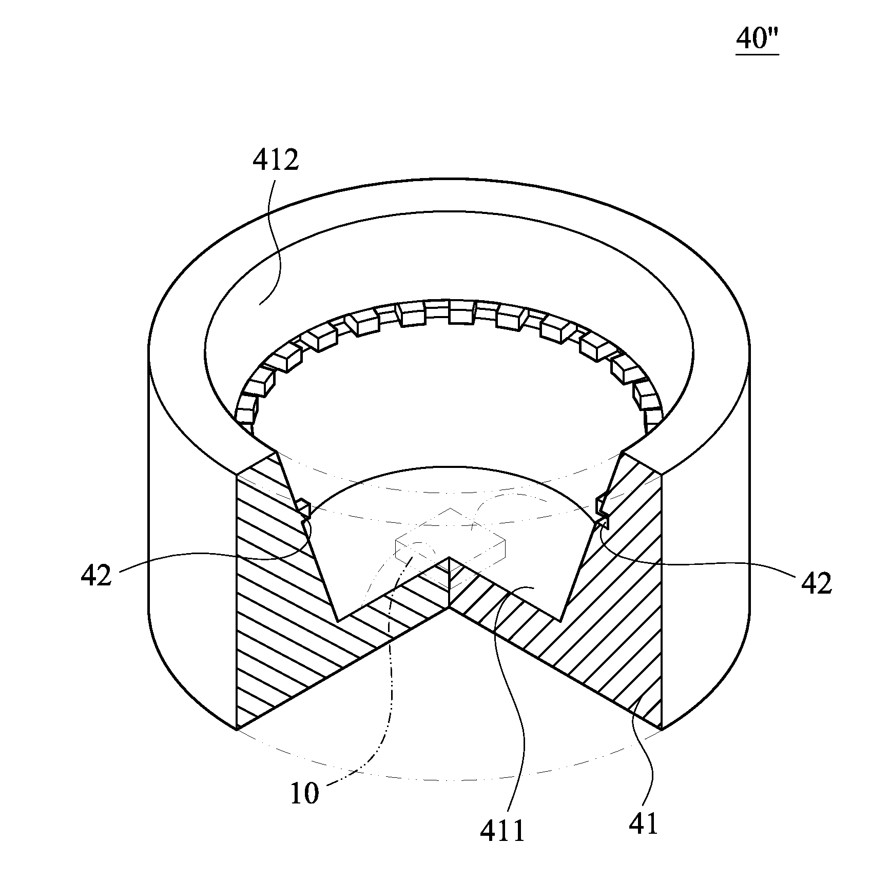
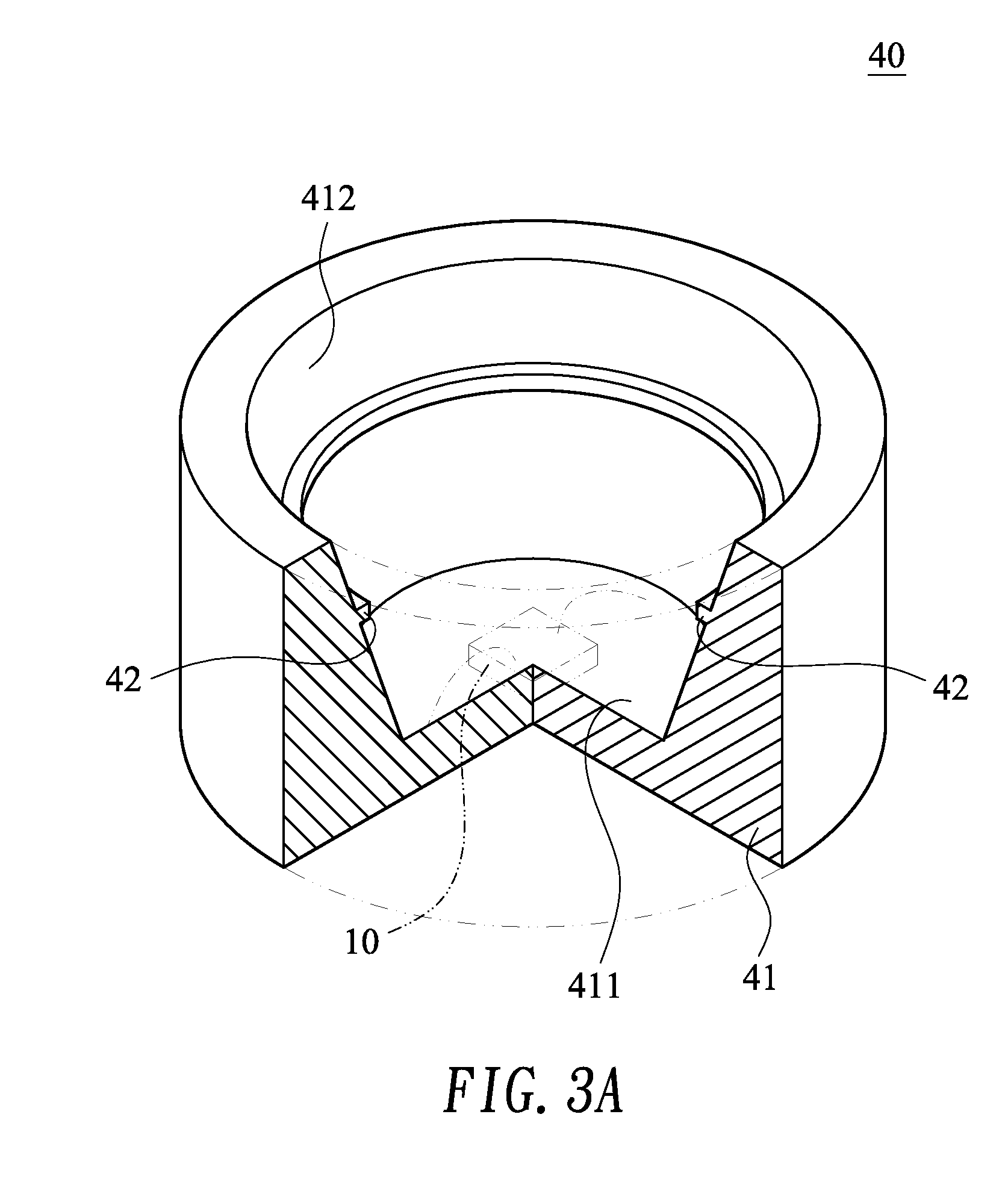
[0066]Please refer to FIG. 3A, FIG. 3B and FIG. 3C. FIG. 3A is a perspective...


PUM


Abstract

A halation-free light-emitting diode holder includes a body and a retaining portion. The body has a die holder, which includes a first surface, a second surface, and an opened end. The retaining portion is provided on the second surface. By using the retaining portion, the optical gel in the die holder is blocked from capillary movement up along the second surface. Furthermore, having nano-material layers further formed on the second surface or having the area of the first surface made greater than the area of the opened-end also prevents the optical gel from climbing along the second surface. Thereby, a light halation circling a light pattern of the resultant light-emitting diode is avoided and the light-emitting diode is improved in luminance uniformity.

Description

BACKGROUND OF THE INVENTION[0001]1. Technical Field[0002]The present invention relates to light-emitting diode holders, and more particularly, to a halation-free light-emitting diode holder that prevents a light-emitting diode from giving a light pattern undesirably circled by a light halation so as to improve the luminance uniformity of the light-emitting diode.[0003]2. Description of Related Art[0004]At present, light-emitting diodes have been supplied as red light-emitting diodes, green light-emitting diodes, and blue light-emitting diodes, each giving the designated color by adopting a different material. However, a light-emitting diode that directly emits white light would be more versatile when used with filters of different colors and serves as a convenient and economical approach to various practical needs. Thus, development of white LEDs has long been targeted by the related researchers and manufacturers.[0005]For example, U.S. Pat. No. 6,351,069 has described the use of a ...

Claims


Application Information

Patent Timeline
IPC IPC(8): F21V21/00H01L33/44H01L33/48H01L33/54H01L33/60
CPCH01L33/44H01L33/486H01L33/507H01L33/54H01L2924/0002H01L33/60H01L2924/00
Inventor CHEN, MING-HUNGWEN, SHIH-YILIN, HSIN-TAICHEN, JING-YI
Owner HELIO OPTOELECTRONICS
Why Eureka
Try Eureka