

Degasifier and liquid chromatograph equipped therewith
a technology of liquid chromatograph and degasifier, which is applied in the direction of liquid degasification, separation process, instruments, etc., can solve the problems of deteriorating measurement accuracy, difficult to accurately measure the concentration of glycohemoglobin, and deteriorating measurement accuracy, so as to increase the degree of pressure reduction
- Summary
- Abstract
- Description
- Claims
- Application Information
AI Technical Summary
Benefits of technology
Problems solved by technology
Method used
Image

Examples
example 1
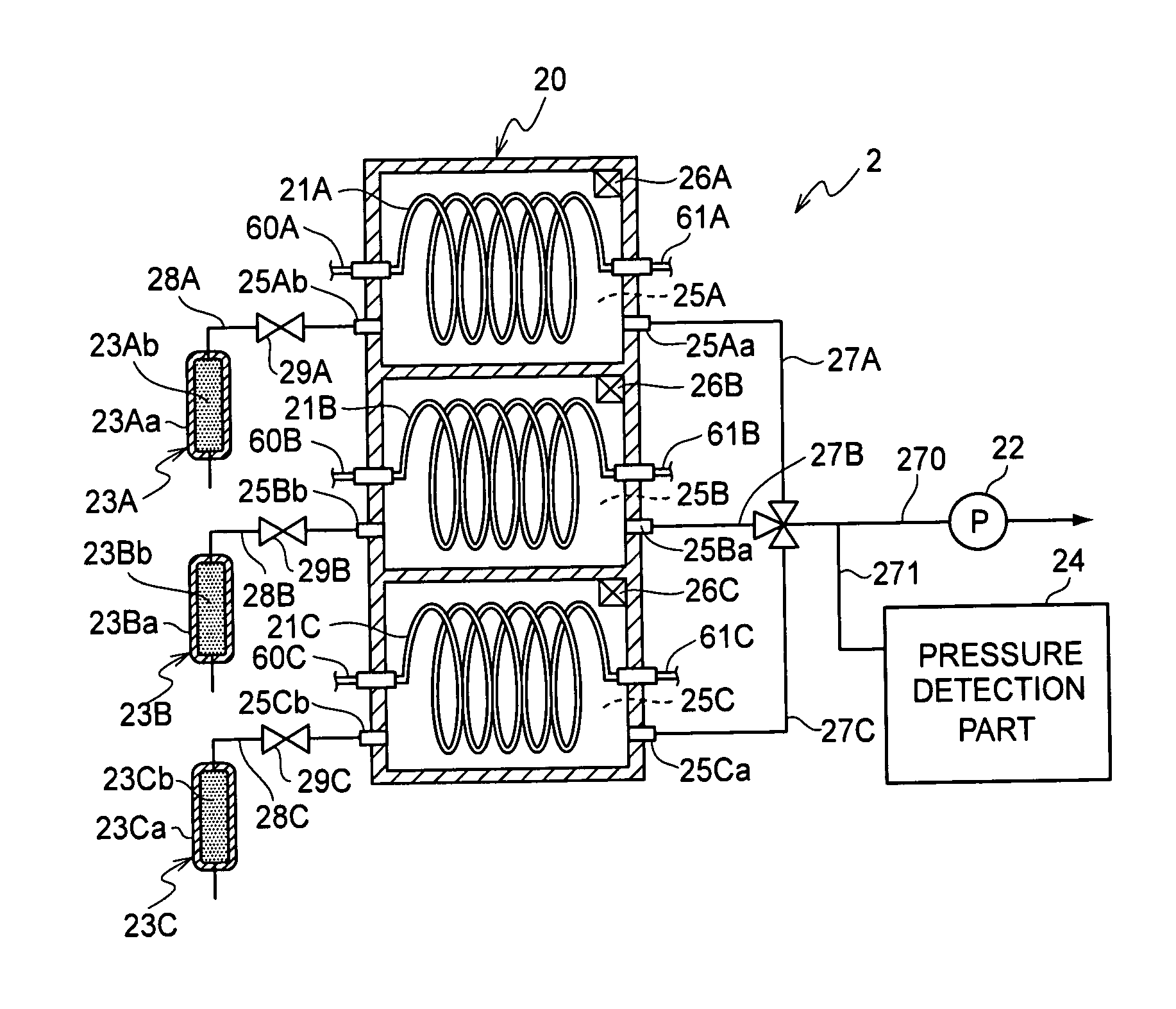
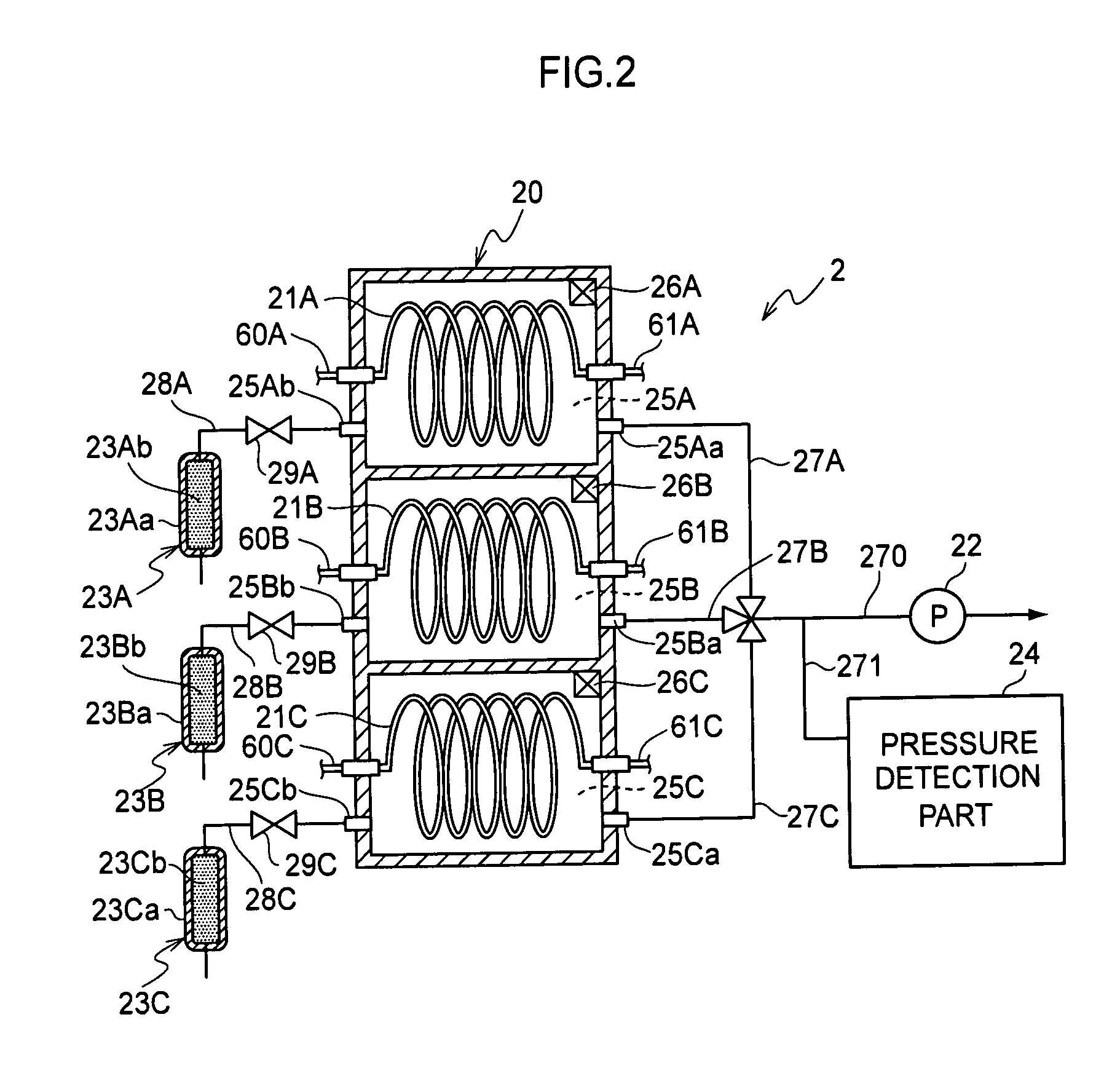
[0140]In the present example, measurements of the glycohemoglobin concentration in a whole blood were serially performed by using a glycohemoglobin measurement apparatus in which the deaerator 7E according to the sixth embodiment of the present invention is adopted (see FIG. 8). The glycohemoglobin measurement apparatus used was an apparatus obtained by improving the deaerator in “ADAMS A1c HA-8160” (manufactured by ARKRAY, Inc.) to the deaerator 7E having the configuration shown in FIG. 8. In the deaerator 7E, the valve 272 provided at an intermediate portion of the exhaust pipes 27A, 27B, 27C, and 270 was omitted. Before starting a measurement for the present Example, a fixed number of samples were continuously measured for glycohemoglobin by the improved glycohemoglobin measurement apparatus, and then the deaerator 7E was stopped. Then, external air was introduced from the exhaust pipes 27A, 27B, 27B, 27C, and 270 and the detection pipe 271 into the reduced-pressure spaces 25A, 2...
PUM
| Property | Measurement | Unit |
|---|---|---|
| absorption maximum wavelength | aaaaa | aaaaa |
| diameter | aaaaa | aaaaa |
| pressure | aaaaa | aaaaa |
Abstract
Description
Claims
Application Information