Refrigerant compressor

a compressor and refrigerant technology, applied in the direction of pump components, positive displacement liquid engines, liquid fuel engine components, etc., can solve the problems of significant loss of contact pressure force, screw connection always requires increased installation effort, and negatively influenced cylindrical shape of the cylinder bor

Active Publication Date: 2010-11-18
SECOP GMBH
View PDF1 Cites 10 Cited by
  • Summary
  • Abstract
  • Description
  • Claims
  • Application Information

AI Technical Summary

Benefits of technology

[0010]It is a further object of the present invention to adapt known refrigerant piston compressors having screwed-on cylinder head so that the occurrence of settling at the seals can be compensated for.

Problems solved by technology

However, the disadvantage has been shown in the case of the use of screw connections that because of the forces which are introduced into the cylinder housing via the fastening screws, the cylindrical shape of the cylinder bore is negatively influenced.
Furthermore, the screw connections always require increased installation effort, because firstly the holes for the fastening screws must be placed in a targeted manner, in order to ensure optimum centering of the cylinder cover relative to the cylinder housing.
A further problem of the widespread solution having screwed-on valve plate and screwed-on valve cover is the settling of the seals and / or the screw connection, which results in a significant loss of contact pressure force due to the rigid design of the screw connection.
However, this construction and the possibility connected thereto of the redesign of the cylinder head also predefine boundary conditions, which allow or require a redesign of the components of the refrigerant piston compressor which are directly or indirectly dependent on the cylinder head.
The implementation of the already known solution having clamped cylinder cover is either not possible at all or is at least not economically feasible in such cases, however.
As is immediately obvious, an implementation of such a solution in the first-described group of refrigerant compressors having screwed-on cylinder head is not possible, notwithstanding the inadequate quality of the clamping connected to this solution.

Method used


Image

  • Refrigerant compressor
  • Refrigerant compressor
  • Refrigerant compressor

Examples


Embodiment Construction

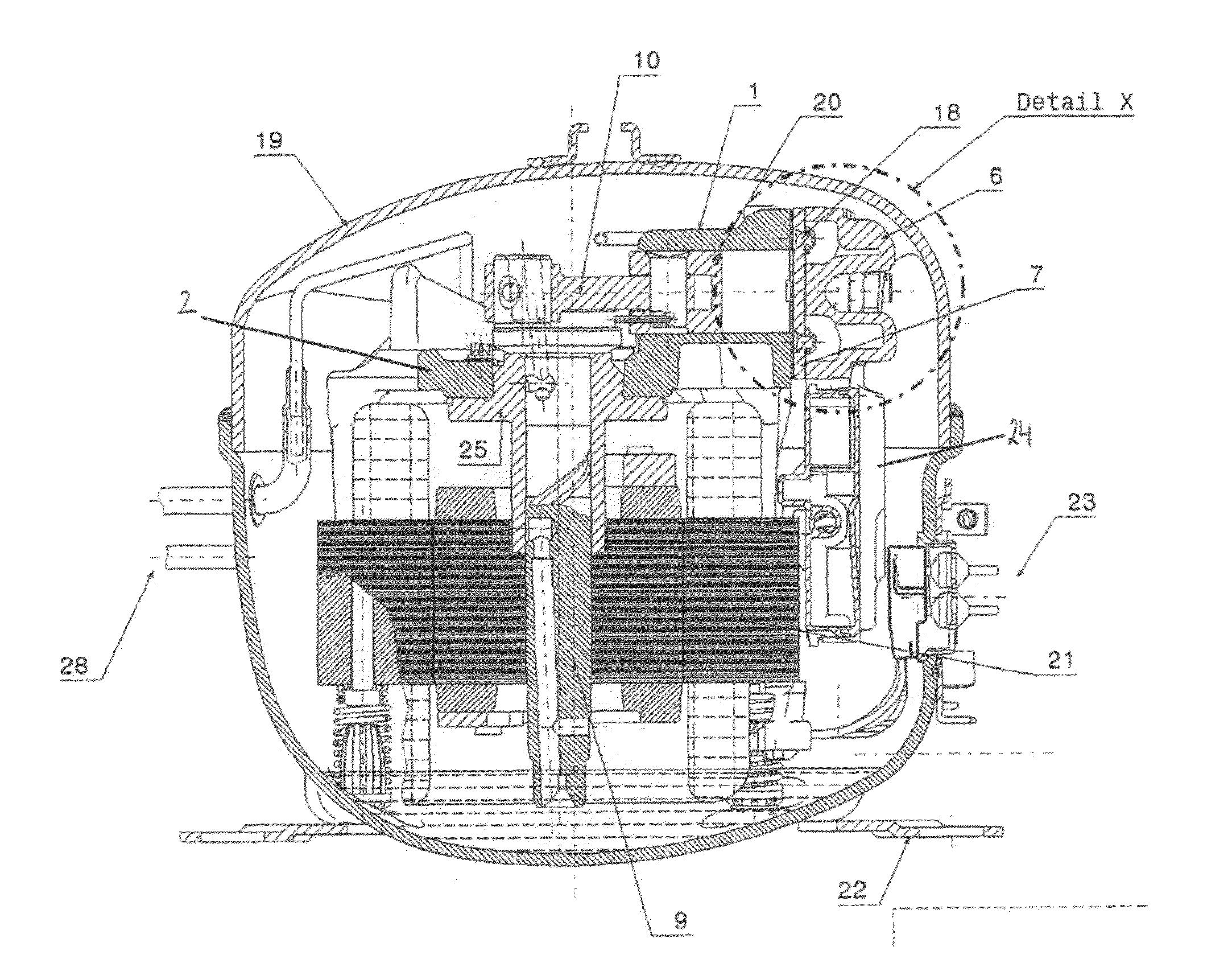
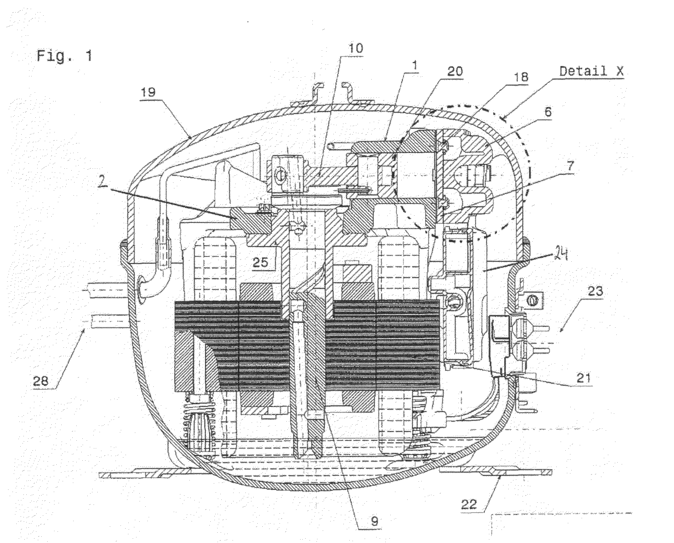
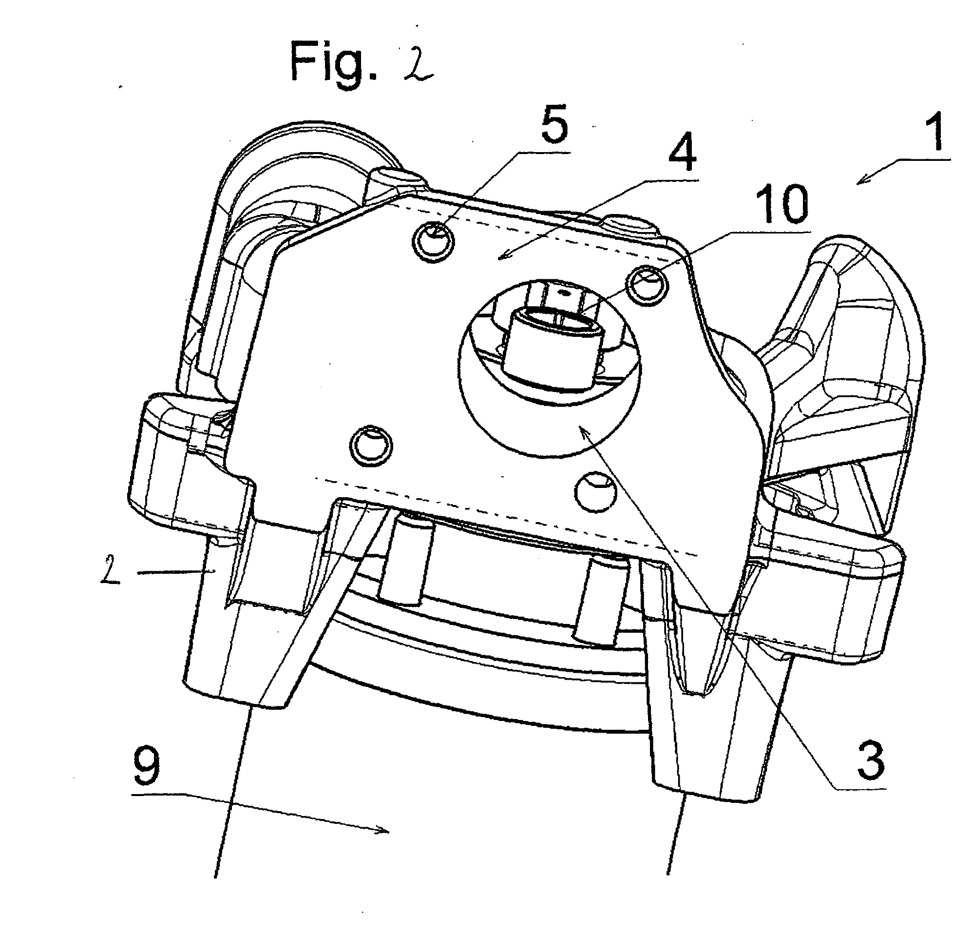
[0011]It is provided according to the invention that in the case of a refrigerant piston compressor for a hermetically encapsulated small refrigerator, which has a piston guided in a piston bore of a cylinder housing and in which the cylinder housing is frontally terminated using a valve plate having a pressure opening and a suction opening and is also frontally provided with holes each having a thread, a first clamping element screwed into the holes is provided, which presses the valve plate against the cylinder housing in the area of at least a section of the piston bore wall and has a pre-tension in the direction of the valve plate in the screwed-on state.

[0012]In this way, typical refrigerant piston compressors, in which the valve plate is screwed onto the cylinder housing, may be adapted accordingly, in that the typical valve plate is replaced with a new one, which is pressed by the clamping element according to the invention against the cylinder housing in the area of the pist...


PUM


Abstract

Refrigerant compressor for a hermetically encapsulated small refrigerator, which has a piston (20) guided in a piston bore (3) of a cylinder housing (1), the cylinder housing being frontally terminated using a valve plate (7) having a pressure opening (17) and a suction opening (16) and also being frontally provided with holes (5), which each have a thread. In order to adapt refrigerant piston compressors having screwed-on cylinder head in such a manner that an energy-efficient redesign of the structure cylinder cover-valve plate-cylinder housing is possible, the changes on the structure required for this purpose simultaneously being minimized, it is provided that a first clamping element (11), which is screwed into the holes (5), is provided, which contacts the valve plate (7) and presses it against the cylinder housing (1) in the area of at least a section of the piston bore wall (14) and has a pre-tension in the direction of the valve plate (7) in the screwed-on state, the clamping element (11) having a clamping section (13), which is located above the piston bore wall (14) in the installed position and has the shape of an imaginary projection of the piston bore wall (14) on the first clamping element (11).

Description

AREA OF THE INVENTION[0001]The present invention relates to a refrigerant piston compressor for a hermetically encapsulated small refrigerator, which has a piston guided in a piston bore of a cylinder housing, the cylinder housing being frontally terminated using a valve plate having a pressure opening and a suction opening and also being frontally provided with holes each having a thread, according to the preamble of claim 1.PRIOR ART[0002]Various types of refrigerant piston compressors are known. The most widespread are those according to whose construction the cylinder housing having the piston bore is frontally closed using a valve plate. The valve plate, in which the suction opening for suctioning the refrigerant out of the refrigerant loop, and the pressure opening, through which the compressed refrigerant is expelled by the piston into the refrigerant loop after the compression procedure are also situated, is screwed onto the front side of the cylinder housing in these most w...

Claims


Application Information

Patent Timeline
Patent Type & Authority Applications(United States)
IPC IPC(8): F04B53/12
CPCF04B39/10F04B39/125F04B39/122F04B39/1066
Inventor FREIBERGER, ALFRED
Owner SECOP GMBH
Why Eureka
Try Eureka