Vacuum adapter for a power tool

Active Publication Date: 2016-09-22
ATLAS COPCO INDAL TECHN AB
View PDF5 Cites 0 Cited by
  • Summary
  • Abstract
  • Description
  • Claims
  • Application Information

AI Technical Summary

Benefits of technology

[0019]The vacuum connection may be arranged on the connection part, such that the cover part may be disconnected from the power tool without affecting the vacuum connection. This is advantageous since often the hose that c

Problems solved by technology

In some applications in the use of power tools the handling of fastener such as screws is particularly cumbersome.
There are however problems involved with this and other vacuum adapters.
A first problem is that the bit may be prematurely worn out.
This problem arises inter alia since an important part of the tightening operations performed by the power tool will be initiated before the bit is correctly located inside the recess of the fastener head.
However, an incorrectly located fastener will in most occasions lead to wear of both the recess of fastener head and the bit in the initial phase of the operation before

Method used


Image

  • Vacuum adapter for a power tool
  • Vacuum adapter for a power tool
  • Vacuum adapter for a power tool

Examples


first embodiment

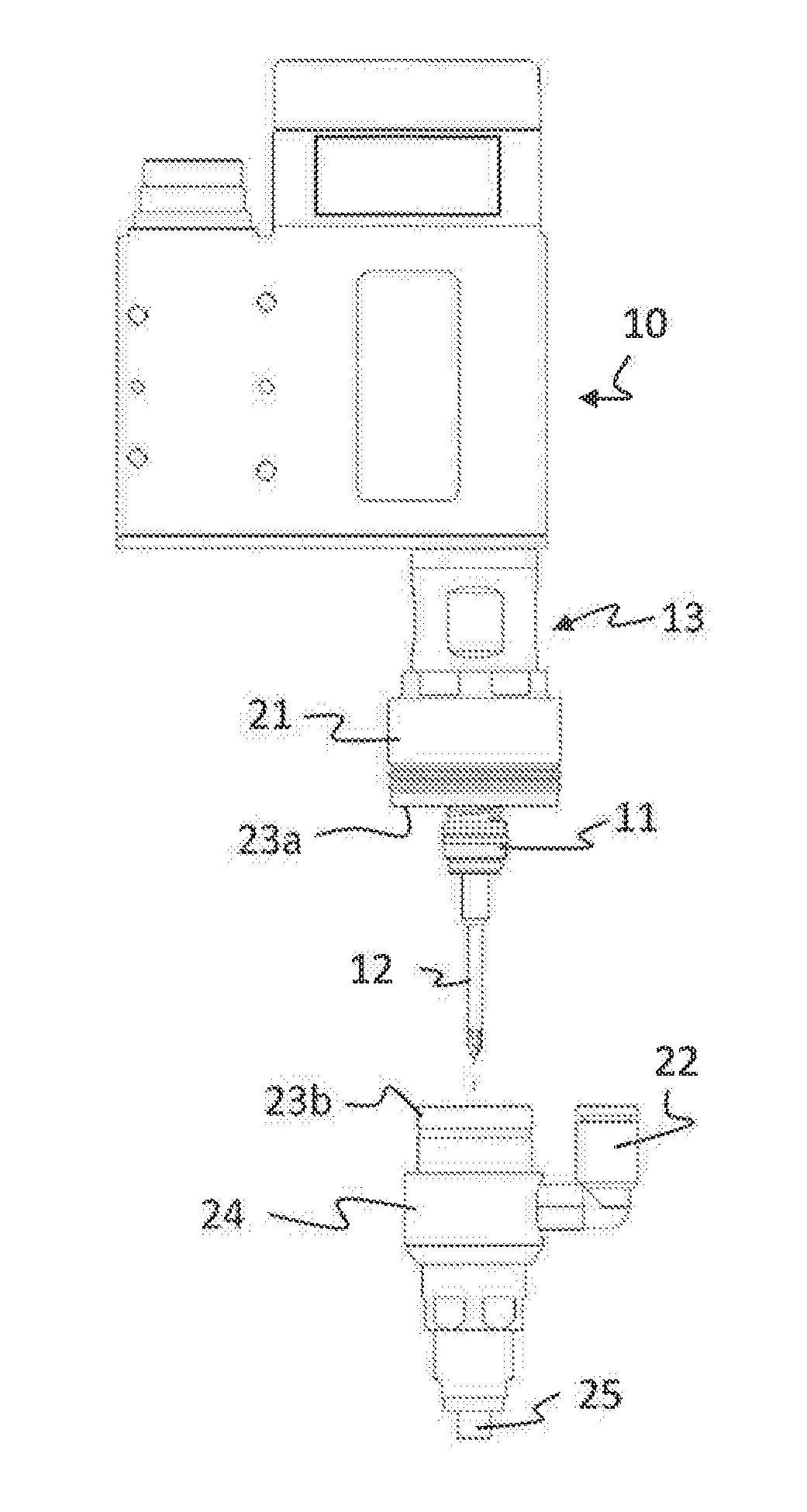
[0035]In FIG. 1 a power tool 10 is shown. A vacuum adapter 20 according to the invention is arranged to a front end 13 of the power tool 10.

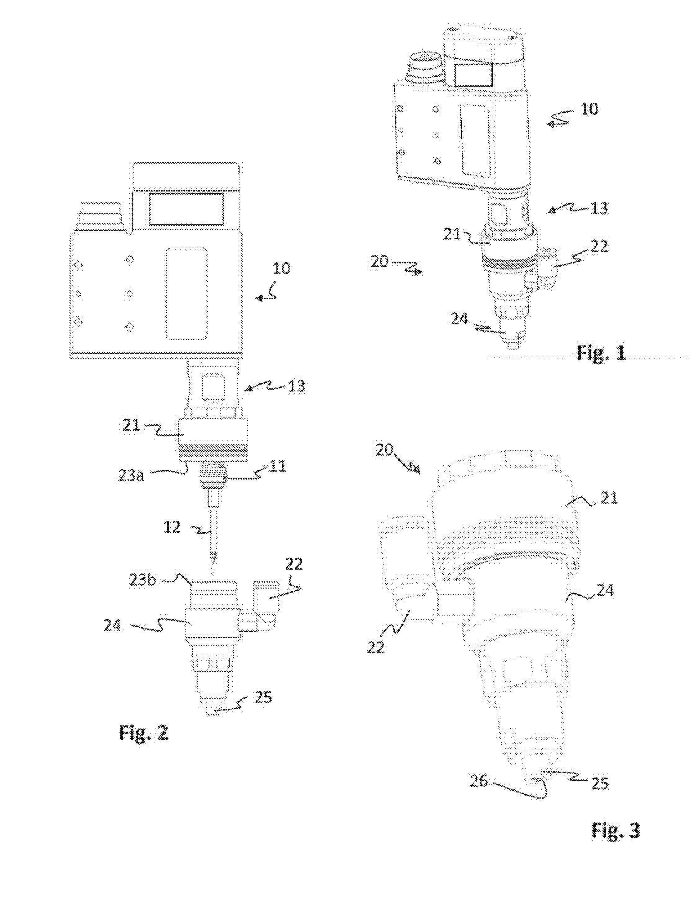
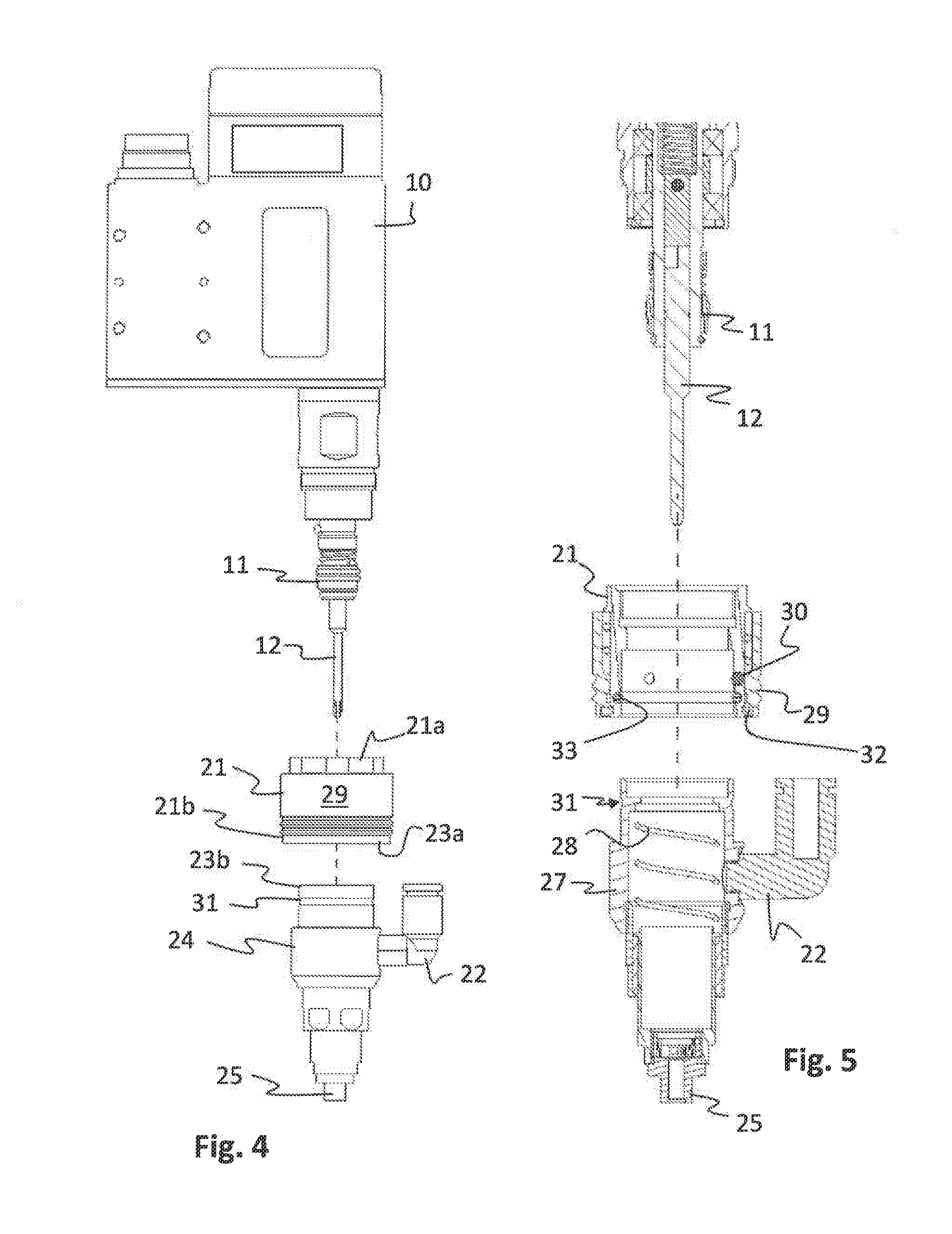
[0036]The vacuum adapter 20 comprises a connection part 21 for connecting the vacuum adapter 20 to the front end 13 of the power tool 10, such that the vacuum adapter 20 covers a bit holder 11 and a tool bit 12 of said tool 10. (See FIG. 2). A vacuum connection 22 for connecting the vacuum adapter 20 to a negative pressure source is arranged on said vacuum adapter. The negative pressure source and the hose connecting the vacuum connection 22 to the negative pressure source are not shown in the figures.

[0037]The vacuum adapter 20 comprises a quick coupling 23a,b for rapid disconnection of at least a part of said vacuum adapter 20 and for easy access to said bit holder 11. This is shown in FIG. 2. The vacuum adapter comprises two main parts, a connection part 21 for connecting the vacuum adapter 20 to the front end 13 of the power tool 10, and a c...

second embodiment

[0046]the inventive vacuum adapter 40 is shown in FIGS. 6-10.

[0047]The vacuum adapter 40 of this second embodiment comprises a connection part 41 for connecting the vacuum adapter 40 to the front end 13 of the power tool 10. A cover part 44 of the vacuum adapter 40 covers the bit holder 11 of the tool 10. The vacuum connection 42 for connecting the vacuum adapter 40 to a negative pressure source is arranged on said connection part 41, such that the cover part 44 may be disconnected from the power tool 10 without affecting the vacuum connection 42. In FIG. 6 the vacuum adapter 40 is shown in position on the power tool 10 and in FIG. 8 it is shown on its own in non-attached mode. As indicated in FIG. 8 the cover part 44 of the vacuum adapter 40 includes a tubular part 45 and a main part 47.

[0048]As is apparent from FIG. 7 a quick coupling 43a,b is arranged for rapid disconnection of the cover part 44 from the connection part 41. The quick coupling includes a female part 43a located on...


PUM


Abstract

A vacuum adapter for a power tool, with a bit holder extending from a front end of the power tool, is arranged to house the bit holder and to suck screws into alignment with a bit arranged inside the bit holder. The vacuum adapter includes: a connection part for connecting the vacuum adapter to the front end of the power tool such that the vacuum adapter covers the bit holder; a vacuum connection for connecting the vacuum adapter to a negative pressure source; a quick coupling for rapid disconnection of at least a part of the vacuum adapter in order to access the bit holder for exchanging bits; and a cover part arranged to cover the bit holder and that is connected to the connection part via a quick coupling and that may be separately disconnected from the power tool, leaving the connection part attached to the power tool.

Description

[0001]The invention relates to a vacuum adapter for a torque delivering power tool. Specifically, the invention relates to vacuum adapter that allows easy access to a bit holder of the tool such that the tool bit of the tool may be replaced without cumbersome efforts and substantially without affecting the settings of the vacuum adapter.BACKGROUND[0002]In some applications in the use of power tools the handling of fastener such as screws is particularly cumbersome. This is especially true for the handling of small screws. For these applications a so called vacuum adapter may be used. The vacuum adapter is an auxiliary device that is adapted to be arranged at the front end of a power tool so as to house the tool bit that is arranged to interact with the fastener to be fastened.[0003]The idea of the vacuum adapter is to suck up a fastener, e.g. a screw, screw head first, such that the screw head will be sucked into the vacuum adapter and into contact with the bit. Subsequently the pow...

Claims


Application Information

Patent Timeline
IPC IPC(8): B25B23/08B23P19/06B25B21/00
CPCB25B23/08B23P19/06B25B21/00B25F5/00
Inventor PARWANI, MAMOONERLANDSSON, JOHAN MATTIASGHASSABEI, JUBIN
Owner ATLAS COPCO INDAL TECHN AB
Why Eureka
Try Eureka