Vehicular air conditioning apparatus

Inactive Publication Date: 2011-01-13
KEIHIN CORP
View PDF10 Cites 15 Cited by
  • Summary
  • Abstract
  • Description
  • Claims
  • Application Information

AI Technical Summary

Benefits of technology

[0011]A general object of the present invention is to provide a vehicular air conditioning apparatus, in which moisture that is generated in a cooling means can be discharged reliably and efficiently to the exterior during times of both running and stopping of the vehicle, without regard to the posture of the vehicle, and together therewith, enabling the vehicular air conditioning apparatus to be made small in size and scale.
[0013]More specifically, with the present invention, by providing the plural drain ports, which communicate between the interior and the exterior of the casing, on the bottom surface of the casing in which the cooling means is installed in the interior thereof, moisture that is generated at the cooling means and which falls therefrom can be quickly and reliably discharged to the exterior through the plural drain ports. Accordingly, by providing a plurality of drain ports, irrespective of the posture of the vehicle, such moisture can be reliably and effectively discharged to the exterior. Further, since a structure is provided by the plural drain ports for discharging moisture to the exterior, the height dimension of the casing having such drain ports can be suppressed and the casing can be made smaller in scale, whereby the vehicular air conditioning apparatus can be accommodated within the limited space of the vehicle.

Problems solved by technology

When such water droplets are left uncontrolled as is, freezing and build-up of ice occurs, thus reducing the effective area of the evaporator, and the heat conversion efficiency of the evaporator is drastically lowered.
Notwithstanding, by adopting such a structure, the dimension in the vertical direction on the bottom surface portion of the casing becomes large, and accommodation of the vehicular air conditioning apparatus within the limited space inside the vehicle is problematic.
Stated otherwise, configuring the vehicular air conditioning apparatus in this manner runs contradictory to efforts to reduce the size and scale of the vehicular air conditioning apparatus.

Method used


Image

  • Vehicular air conditioning apparatus
  • Vehicular air conditioning apparatus
  • Vehicular air conditioning apparatus

Examples


first embodiment

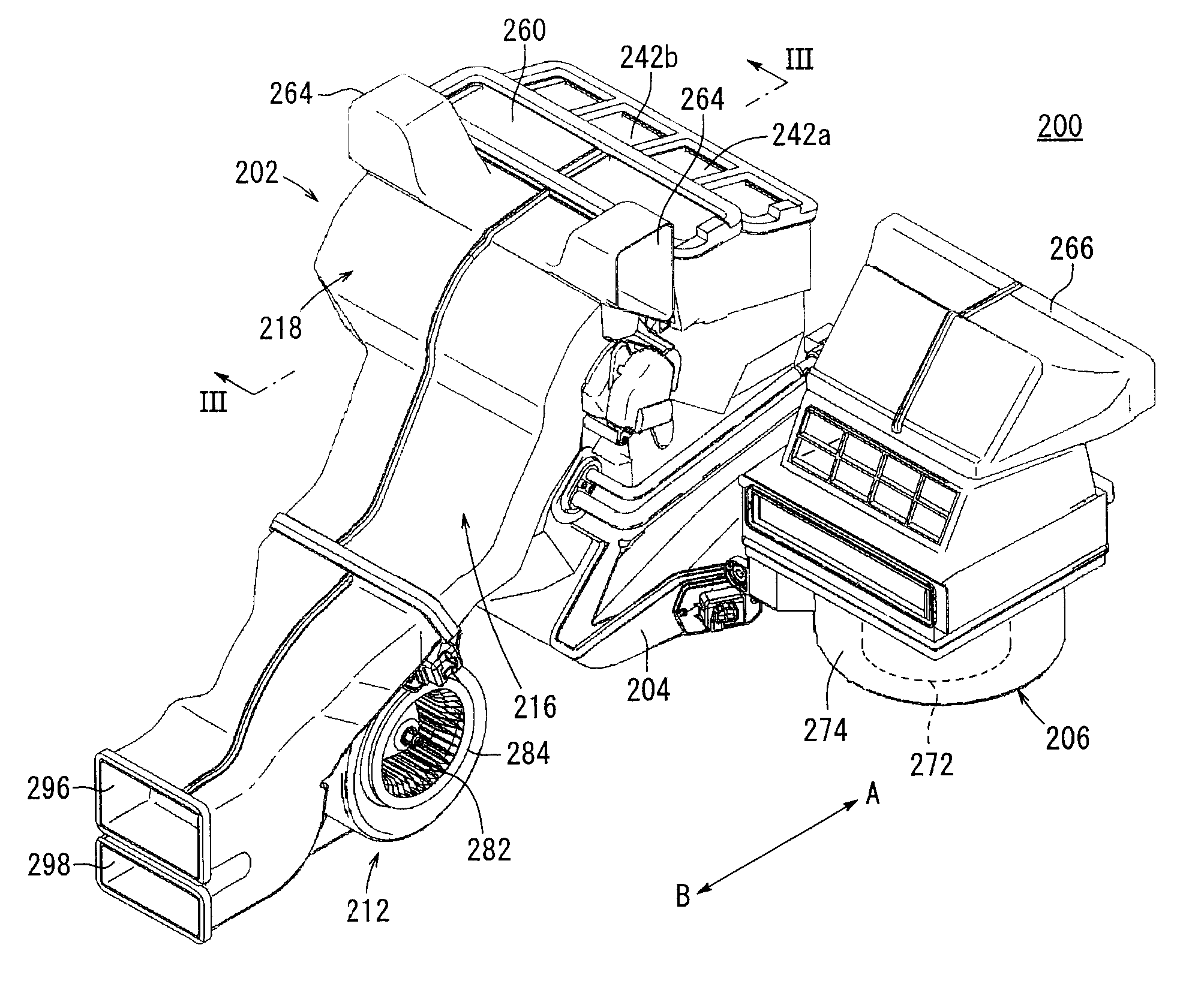
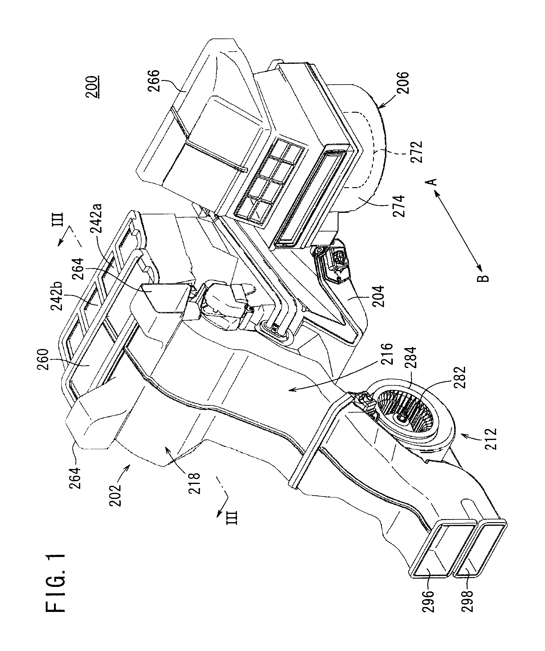
[0071]A preferred embodiment of a vehicular air conditioning apparatus according to the present invention shall be presented and explained in detail below with reference to the accompanying drawings. In FIG. 1, reference numeral 200 indicates a vehicular air conditioning apparatus according to the present invention. The vehicular air conditioning apparatus 200, for example, is installed in a vehicle having three rows of seats arranged along the direction of travel of the vehicle. In the following descriptions, the first row of seats in the vehicle compartment of the vehicle is designated as front seats, the second row of seats is designated as middle seats, and the third row of seats is designated as rear seats.

[0072]Further, the vehicular air conditioning apparatus 200 is installed so that the righthand side thereof shown in FIG. 2 (in the direction of arrow A) is oriented toward the front side of the vehicle, whereas the lefthand side (in the direction of arrow B) is oriented towa...

second embodiment

[0130]Next, a vehicular air conditioning apparatus 400 is shown in FIGS. 10 to 53. FIG. 11 is a cross sectional view in a central portion (taken along line XI-XI in FIG. 10) along the widthwise direction of a vehicular air conditioning apparatus 400, whereas FIG. 12 is a cross sectional view of a region (taken along line XII-XII in FIG. 10) somewhat deviated to the side of a second divided casing 418 from the aforementioned central portion.

[0131]As shown in FIGS. 10 to 14, the vehicular air conditioning apparatus 400 according to the second embodiment includes a casing 402 constituted by respective air passages, a first blower unit 406 connected through a connection duct 404 to a side portion of the casing 402 for blowing air to the front seats in the vehicle, an evaporator (cooling means) 408 arranged inside the casing 402 for cooling the air, a heater core 410 for heating the air, a second blower unit 412 connected to a lower portion of the casing 402 for blowing air toward the m...


PUM


Abstract

A vehicular air conditioning apparatus is equipped with a casing having respective air passages therein, and first and second blower units are connected to the casing. Further, the casing is constituted by first and second divided casings. In addition, air is supplied to the interior of the casing from the first and second blower units. Moisture, which is generated when the air is cooled by an evaporator, is guided to forward bottom surfaces of the first and second divided casings and the moisture is discharged to the exterior from first drain ports disposed at terminal end positions of inclined surfaces that decline gradually toward opposite sides of the casing.

Description

BACKGROUND OF THE INVENTION[0001]1. Field of the Invention[0002]The present invention relates to a vehicular air conditioning apparatus mounted in a vehicle for blowing air into a vehicle compartment that has been adjusted in temperature by a cooling means, for thereby adjusting temperature of the vehicle compartment.[0003]2. Description of the Related Art[0004]In a vehicular air conditioning apparatus that is mounted in a vehicle, internal and external air is introduced into a casing by a blower, and after cooled air, which has been cooled by an evaporator that forms a cooling means, and heated air, which has been heated by a heater core that forms a heating means, are mixed together in the casing at a predetermined mixing ratio, the mixed air is blown out from a defroster blow-out port, a face blow-out port, or a foot blow-out port, whereby adjustment of temperature and humidity in the vehicle compartment is carried out.[0005]With this type of vehicular air conditioning apparatus,...

Claims


Application Information

Patent Timeline
IPC IPC(8): B60H1/00
CPCB60H1/00064B60H1/00678B60H2001/002B60H2001/00099B60H2001/00135B60H1/3233
Inventor SETO, TAKAHIRO
Owner KEIHIN CORP
Why Eureka
Try Eureka