Image forming apparatus

Active Publication Date: 2011-01-13
CANON KK
View PDF5 Cites 5 Cited by
  • Summary
  • Abstract
  • Description
  • Claims
  • Application Information

AI Technical Summary

Benefits of technology

[0012]A principal object of the present invention is to provide an image forming apparatus capable of decreasing a degree of improper charging caused by deposition, on a charging device, of s

Problems solved by technology

Specifically, a rubber member exhibiting a sufficient cleaning property even in a low-temperature environment in which the rubber elasticity is liable to be lost.
This causes an occurrence of a stripe on an image or image blur (density fluctuation or the like) during subsequent image formation.
In order to essentially solve the above problem, it is not reliable that the cleaning blade is retracted from the photosensitive drum surface when the image forming apparatus is in a rest state.
However, in this case, a retracting mechanism is costly.
It is difficult to ensure accuracy of the contact state, thus re

Method used


Image

  • Image forming apparatus
  • Image forming apparatus
  • Image forming apparatus

Examples


Example

Embodiment 1

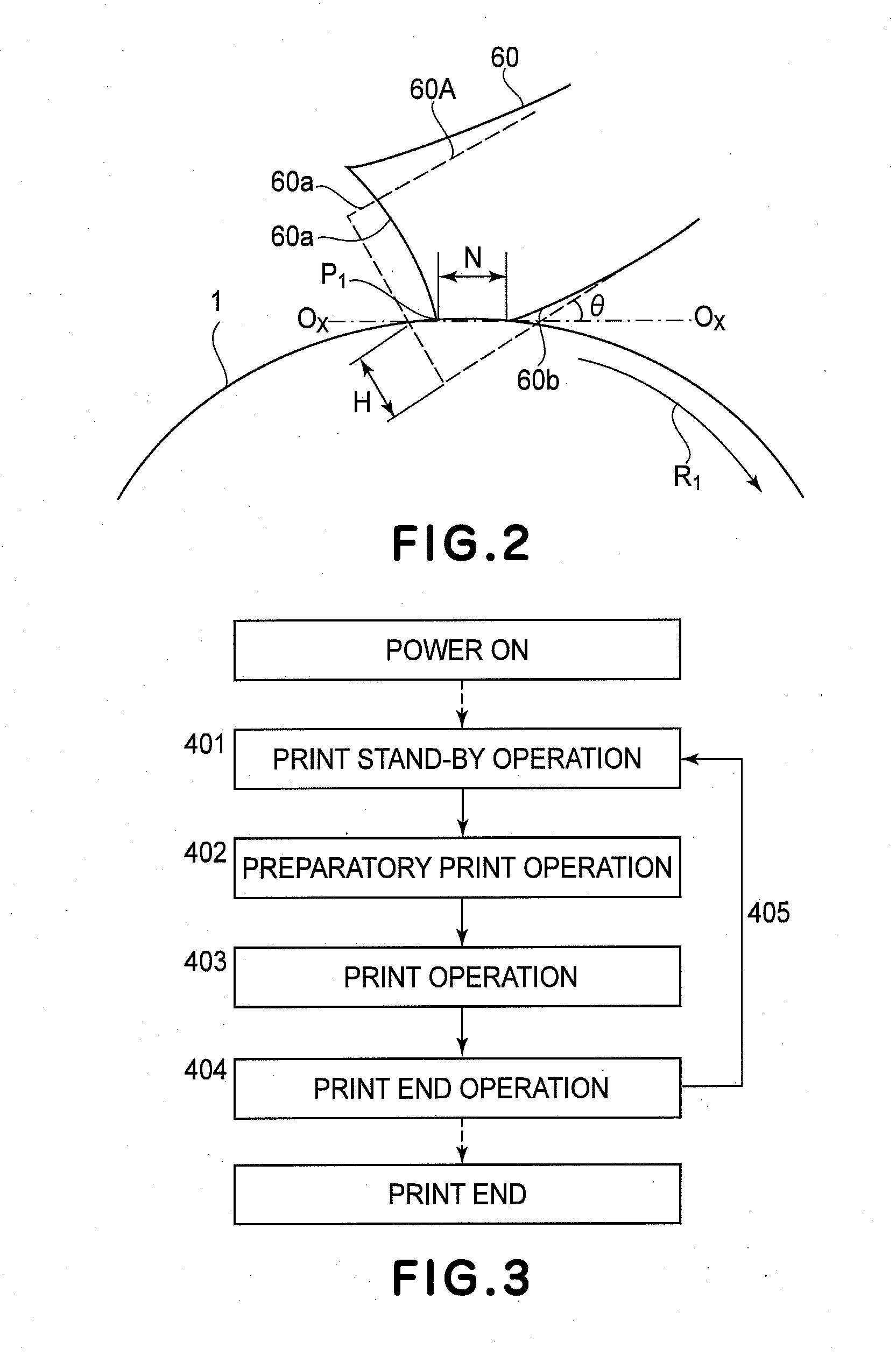
[0025]Embodiment 1 of the present invention will be described. In this embodiment, an “image forming area” refers to an area of a photosensitive drum in which an image (latent image or toner image) to be subjected to image formation on a recording material (recording medium) as a toner image receiving member is to be formed. Further, “during image formation” refers to a period of time when respective process means for charging, exposure, development, transfer, and the like act on the photosensitive drum in the image forming area. Strictly speaking, during image formation with respect to the charging and during image formation with respect to the transfer refer to different periods of time. Further, “during non-image formation” refers to a period of time except the “during image formation”.

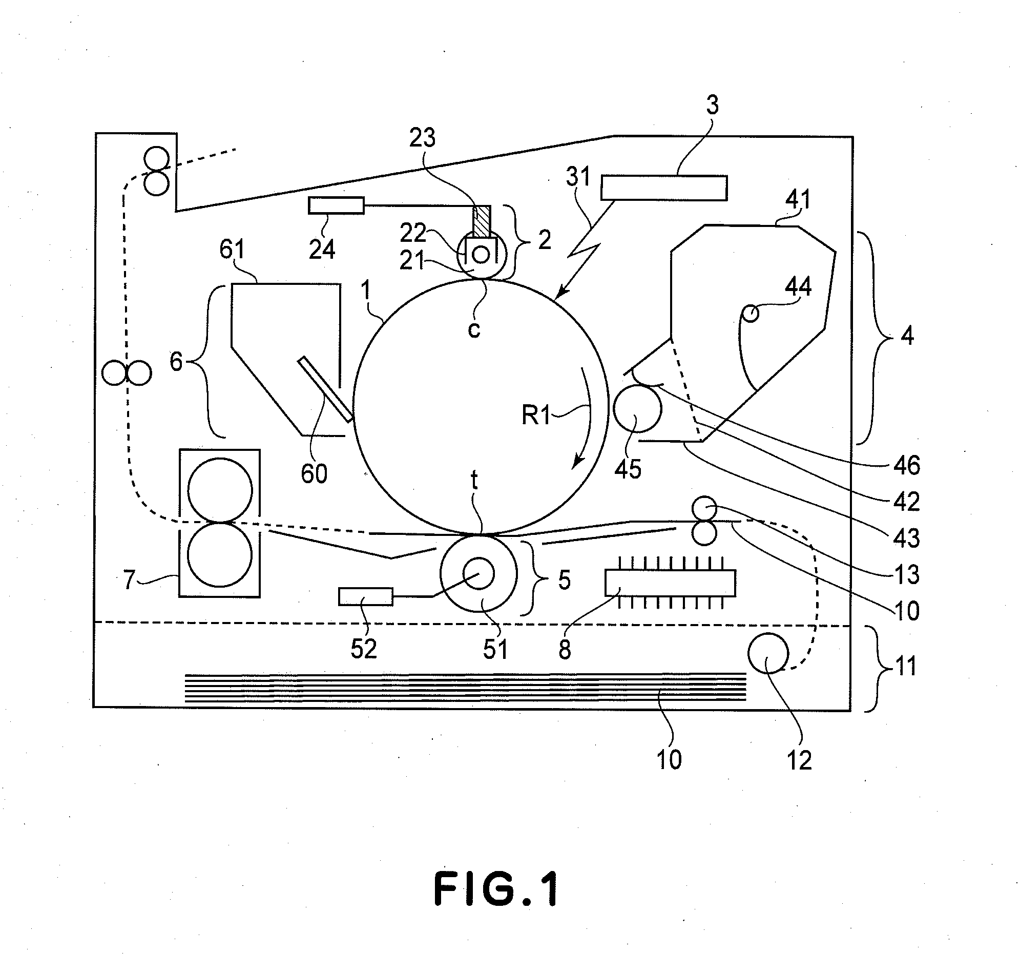
[0026]FIG. 1 is a schematic illustration of the image forming apparatus in this embodiment. In this embodiment, at a central portion of the image forming apparatus, a drum-like electrop...

Example

Embodiment 2

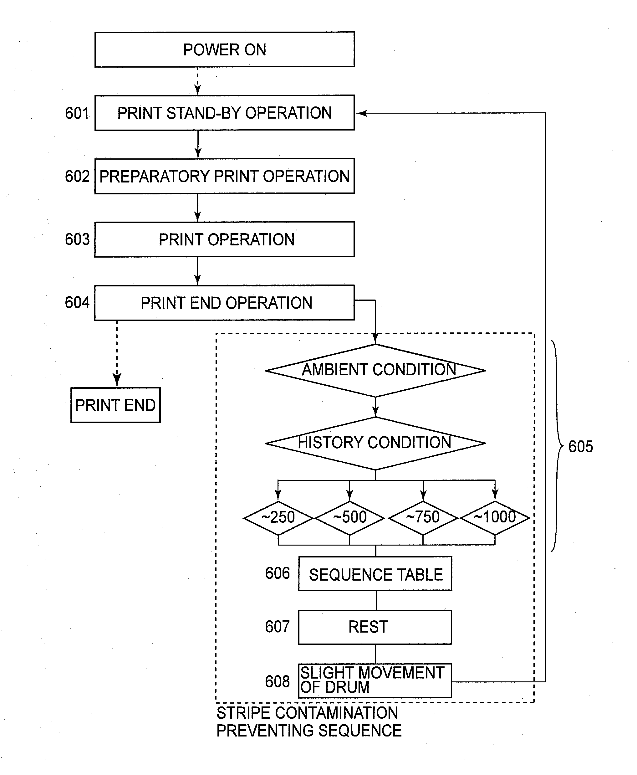
[0095]In Embodiment 1, it was possible to decrease a degree of the occurrence of the image defect resulting from the drive stripe substance by rotating the photosensitive drum during the print stand-by period. However, as a result of an experiment, the drive stripe contamination is liable to occur in a high-temperature and high-humidity environment rather than a low-temperature and low-humidity environment. This may be attributable to a phenomenon such that the drive stripe substance is increased in viscosity and adhesive property in the high-temperature and high-humidity environment and is liable to accumulate on the cleaning blade nip downstream side. As described above, such a result that the accumulation amount of the drive stripe substance is small depending on the disposition environment is also obtained. Further, as a condition in which the drive stripe substance is liable to accumulate on the cleaning blade nip downstream side, in addition to the case where the p...

Example

Embodiment 3

[0115]In Embodiment 1, by rotating the photosensitive drum during the print stand-by period, it was possible to decrease the degree of the occurrence of the image defect caused due to the drive stripe contamination. However, in the sequence described in Embodiment 1, the degree of the occurrence of the drive stripe contamination can be decreased but the drive stripe contamination slightly occurs in some cases.

[0116]FIG. 10 shows relaxation of the strain after the printing on 1000 sheets is effected in the case where the sequence is executed. At the stand-by time of 45 minutes, the strain amount is once increased. This is attributable to the execution of the sequence. The relaxation of the cleaning blade strain is continued also during a period from the completion of the execution of the sequence to provision of a subsequent print instruction. As shown in FIG. 11(c), with respect to the drive stripe substance T5 separated and dropped from the cleaning blade when the drive...


PUM


Abstract

An image forming apparatus includes a rotatable drum; a charging roller, contacting the drum, for electrically charging the drum; a developing device for developing a latent image formed on the drum into a developer image; and a cleaning device for removing a developer remaining on the drum after the developer image is transferred from the drum onto a developer image receiving member. The cleaning device includes a cleaning blade contacting the drum and having a fixed end and a free end which is located upstream of the fixed end with respect to a rotational direction of the drum. The image forming apparatus further includes a control device for controlling a rotating operation of the drum. The control device is capable of performing an operation for rotating the drum, in a direction identical to the rotational direction of the drum during image formation effected by rotating the drum, after a lapse, without next instruction of image formation, of a predetermined period from a stop of rotation of the drum once made after completion of the image formation. The predetermined period is longer with a larger number of sheets subjected to the image formation in an image forming job before the rotation of the drum is stopped.

Description

FIELD OF THE INVENTION AND RELATED ART[0001]The present invention relates to an image forming apparatus of an electrophotographic type, such as a copying machine, a printer or a facsimile machine. More specifically, the present invention relates to the image forming apparatus including a drum-like electrophotographic photosensitive member (hereinafter referred to as a “photosensitive drum”), a contact charging device for electrically charging the surface of the photosensitive drum, and a cleaning member for cleaning the surface of the photosensitive drum (hereinafter referred to as a “cleaning blade”).[0002]As the image forming apparatus of the electrophotographic type, e.g., there is the image forming apparatus of an ordinary transfer type using an electrophotographic process represented by a Carlson process. In such an image forming apparatus, the photosensitive drum as an image bearing member is repeatedly used. For that reason, a charging device is required for removing a transf...

Claims


Application Information

Patent Timeline
IPC IPC(8): G03G15/00
CPCG03G15/5008
Inventor NAITO, NORIHITOKIHARA, TAKAYOSHIKATO, MASAHITOKASE, TAKASHI
Owner CANON KK
Why Eureka
Try Eureka