Handrail assembly and method

Active Publication Date: 2011-01-27
9220 6820 QUEBEC
View PDF20 Cites 20 Cited by
  • Summary
  • Abstract
  • Description
  • Claims
  • Application Information

AI Technical Summary

Benefits of technology

[0007]It is the object of the present invention to provide a secure handrail assembly for users with impaired mobility, this sy

Problems solved by technology

Stroke victims are often incapable of using a walker requiring strength in both arms and must have secure railings to remain ambulatory.
However, this uses regular screws to attach the rail to the clamps, and requires a lot more ti

Method used


Image

  • Handrail assembly and method
  • Handrail assembly and method
  • Handrail assembly and method

Examples


Embodiment Construction

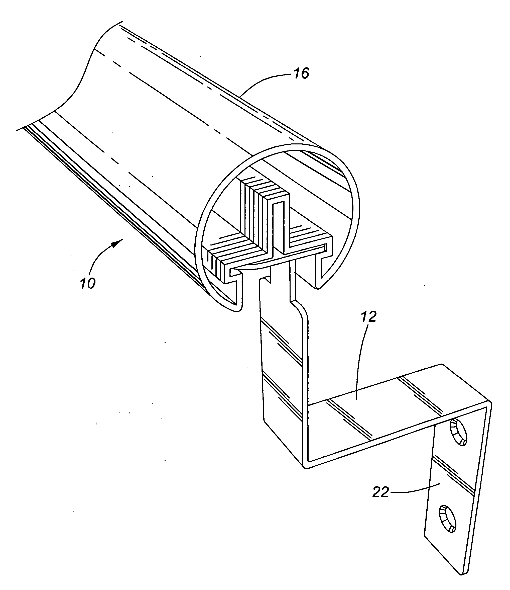
[0029]The present invention can be represented in many different variants. However, the essence of this invention resides in its ability to provide a stable handrail in almost any setting, providing there is a wall. The following two variants of the preferred embodiment are based on the objective to reduce manufacturing costs yet provide a product that can bear the weight of an average person.

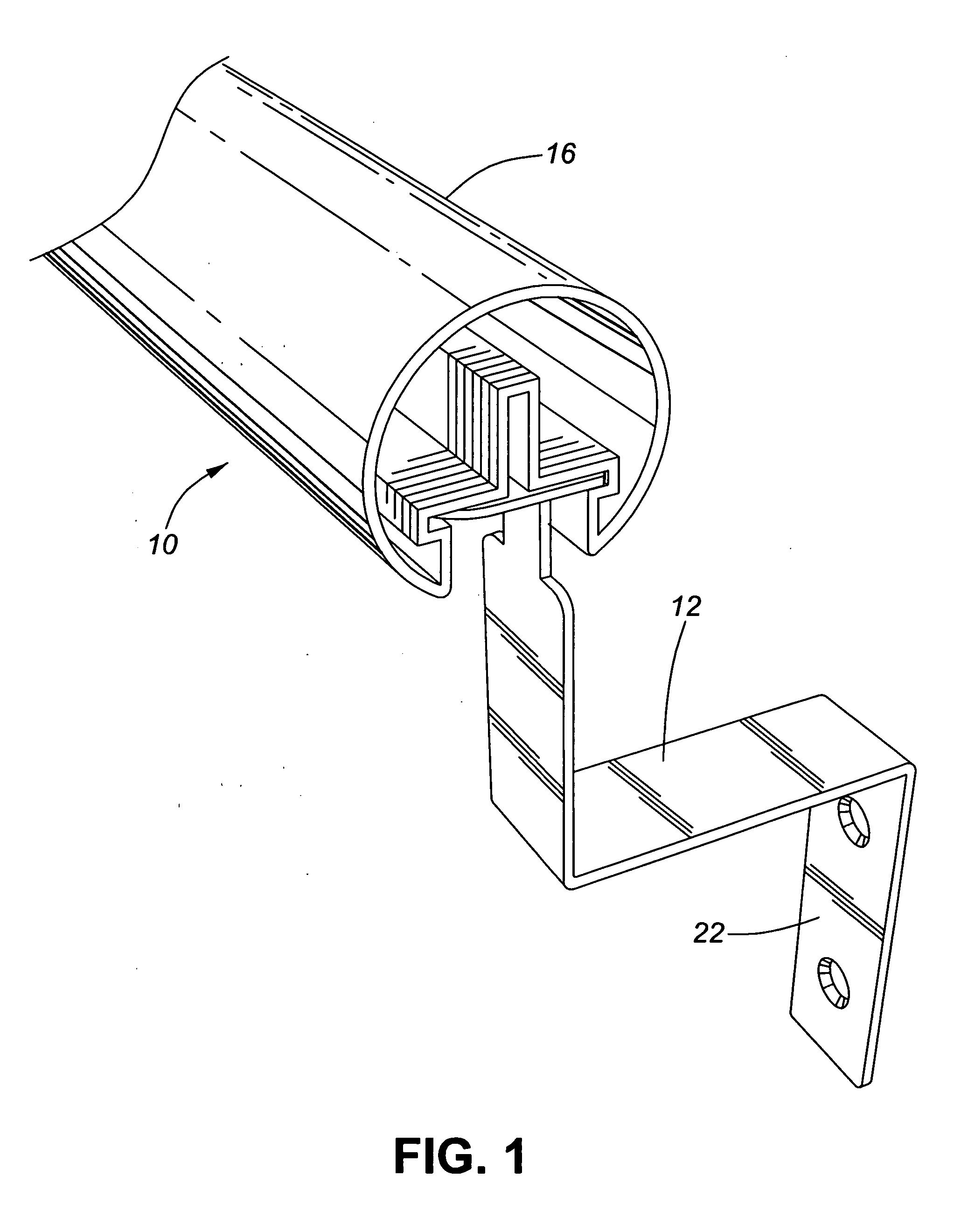
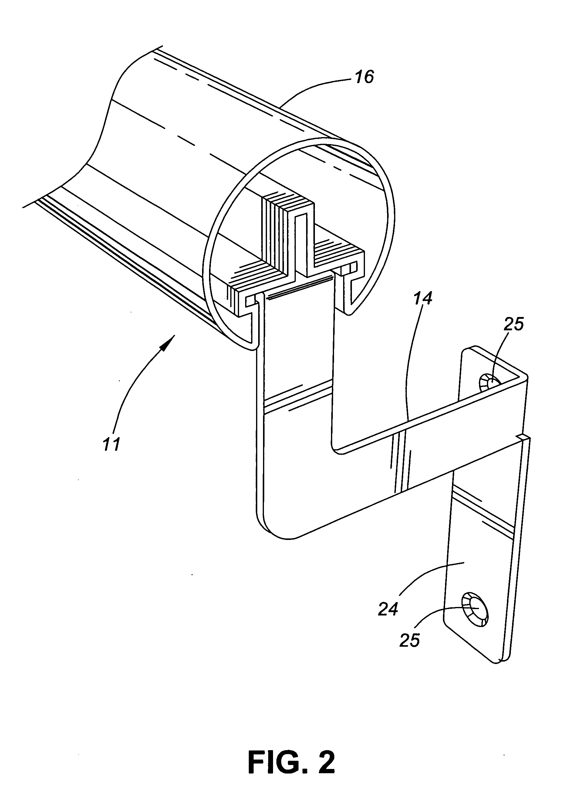
[0030]Referring now to figures, FIG. 1 shows Variant 1 of the present invention. This variant comprises assembly 10, consisting of bracket 12 and railing 16. FIG. 2 shows Variant 2, comprising assembly 11, consisting of bracket 14 and railing 16.

[0031]FIG. 3 shows the bracket 12 of Variant 1, comprising wall support portion 19, handrail attachment means or head 26 comprising rounded corner or tongue element 30 and ears 36, and handrail support means 21 comprising of horizontal support arm 40 and vertical support arm 41. Wall support portion 19 comprises two holes 23; support arm 40 extends hori...


PUM

PropertyMeasurementUnit
Fractionaaaaaaaaaa
Fractionaaaaaaaaaa
Angleaaaaaaaaaa

Abstract

This invention relates to a handrail assembly that can be installed on any wall. The assembly consists of a handrail and a bracket. The bracket can be twist-locked inside the handrail at any point in the handrail because the handrail has a continuous T-shaped channel at the bottom. The T-shaped channel's bottom portion is narrower than the upper portion. The bracket has a head that is as wide as the T-shaped channel's bottom portion and as long as the T-shaped channel's upper portion. The head has one curved corner to facilitate turning and teeth to bite into the upper portion of the channel's wall. The head is lifted through the bottom portion into the upper portion of the channel, the bracket is rotated a quarter turn, and the bracket becomes immobilized. The head of the bracket acts as a cam. Union joints can join multiple lengths of handrails.

Description

[0001]This application is based on the provisional patent application 61 / 213,858 filed on Jul. 22, 2009. The present invention relates to a handrail assembly, and more particularly to an assembly that can be easily attached to almost any place where ambulatory support is necessary, being a wall in a residence, inhabited space, or outside vertical surface. This assembly is easy to install, remove, and very inexpensive to manufacture. It provides a modular solution to the growing population of aging citizens, and can extend a user's period of independent home living by several years.BACKGROUND OF THE INVENTION[0002]Demographic statistics show an aging population. Older people are more prone to injuries and ailments that impair their mobility, and benefit from installation of railings that minimize risk of falling. Stroke victims are often incapable of using a walker requiring strength in both arms and must have secure railings to remain ambulatory. Railings are especially important in...

Claims


Application Information

Patent Timeline
IPC IPC(8): E04F11/18B23P11/00
CPCE04F11/1836Y10T29/49826E04F11/1838
Inventor REICH, DAVID
Owner 9220 6820 QUEBEC
Why Eureka
Try Eureka