Apparatus for wellhead high integrity protection system

a protection system and high integrity technology, applied in water supply installation, braking system, valve type, etc., can solve the problems of not providing safety information of the overall system's ability to perform safety functions, the failure of conventional systems to test during their operation, and serious financial consequences of interruption of operations

Active Publication Date: 2011-03-10
SAUDI ARABIAN OIL CO
View PDF16 Cites 9 Cited by
  • Summary
  • Abstract
  • Description
  • Claims
  • Application Information

AI Technical Summary

Benefits of technology

[0020]In a preferred embodiment, the safety logic solver is programmed to maintain one set of the SSVs in an open position when the parallel set of SSVs is moved to a closed position from an open position during a full-stroke test. In addition, the safety logic solver is programmed to measure and record the pressure between a pair of the closed SSVs during a tight shut-off test, and to open the VCV between the closed SSVs for a short period of time during the test to relieve or reduce the line pressure.

Problems solved by technology

It is a necessary requirement that the safety of the HIPS be tested regularly since a malfunction in operation of the HIPS presents the risk of significant damage to the pipeline.
The conventional system cannot be tested during its operation.
The interruption of operations has serious financial implications.
This test system is useful for testing surface safety valves in hydraulic circuits, but does not provide safety information of the overall system's ability to perform safety function.
This system, however, has to interrupt production for the diagnostic testing.
The protection system, however, does not provide any valve diagnostic means and is forced to interrupt the production for shut off valves to be fully closed.
This system does not permit a testing of shut off valves without an interruption of production.
This method, however, requires that the production be interrupted for the testing of the hydraulic system.
The system results in an interruption of production and operators intervention.

Method used


Image

  • Apparatus for wellhead high integrity protection system
  • Apparatus for wellhead high integrity protection system
  • Apparatus for wellhead high integrity protection system

Examples


Embodiment Construction

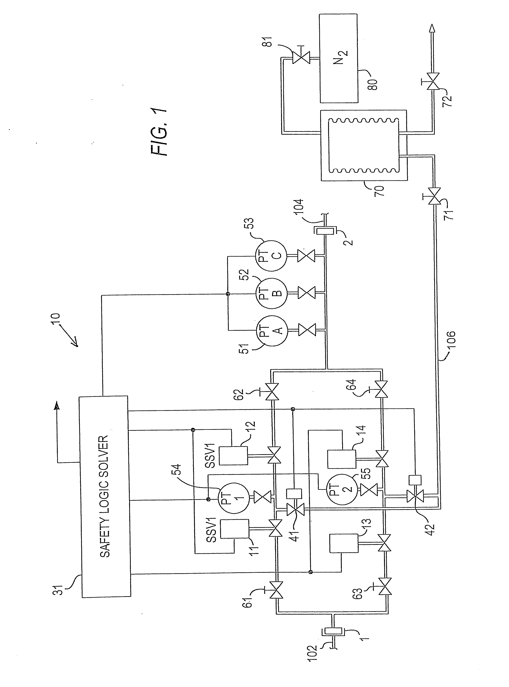
[0036]Referring to FIG. 1, a high integrity protection system (HIPS) 10 is installed in proximity to a wellhead in a piping system to convey a pressurized fluid product, such as oil or gas, from the wellhead 102 to a remote host location via pipeline 104. The HIPS has an inlet 1 connected to the wellhead piping 102 and an outlet 2 connected to piping system 104 through which the liquid product enters and exits the HIPS 10. The HIPS is preferably skid-mounted for delivery to the site of the wellhead and is provided with appropriate flanges and adapters, if necessary, for attachment to the inlet and outlet to the oil field piping.

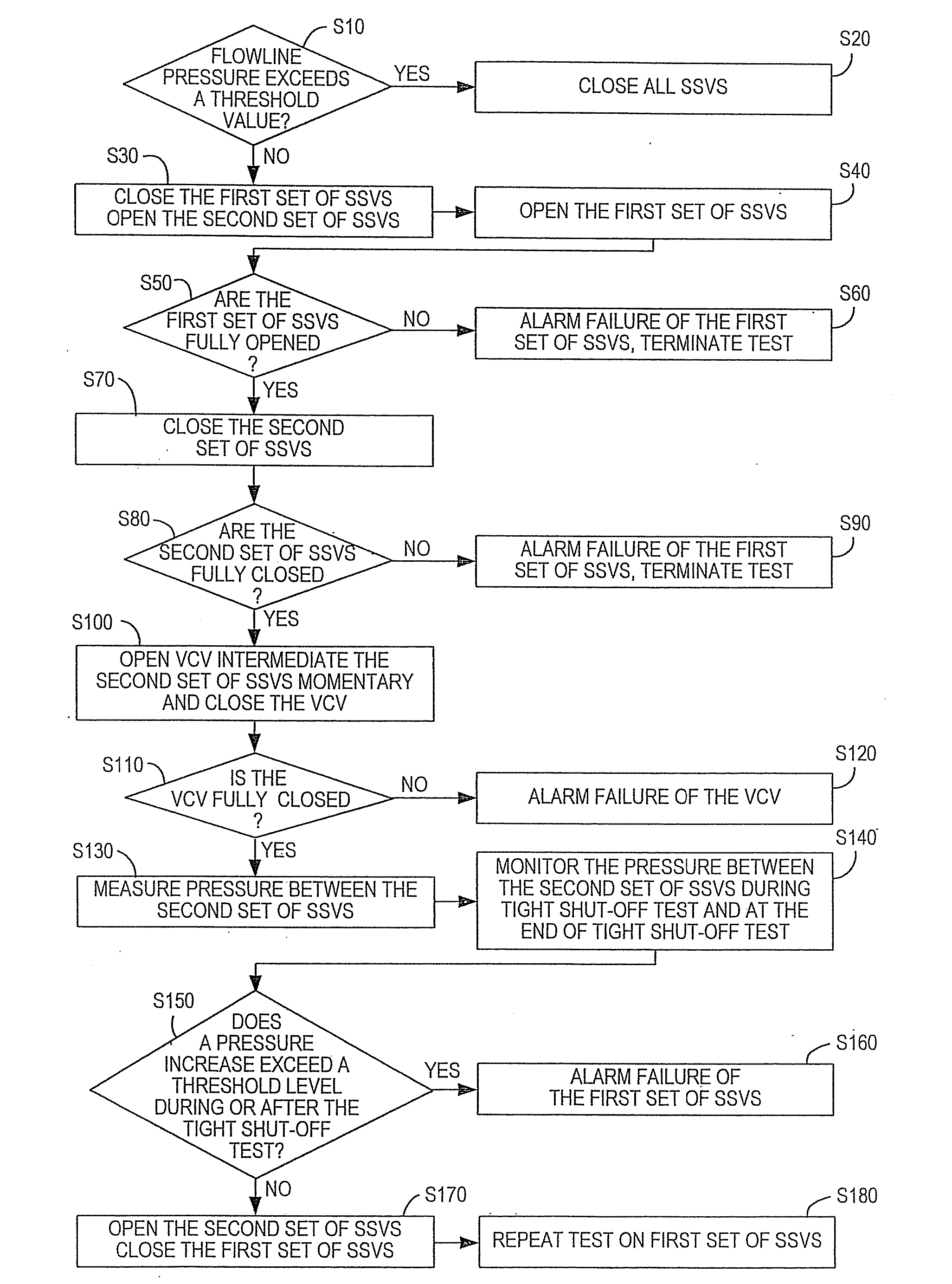
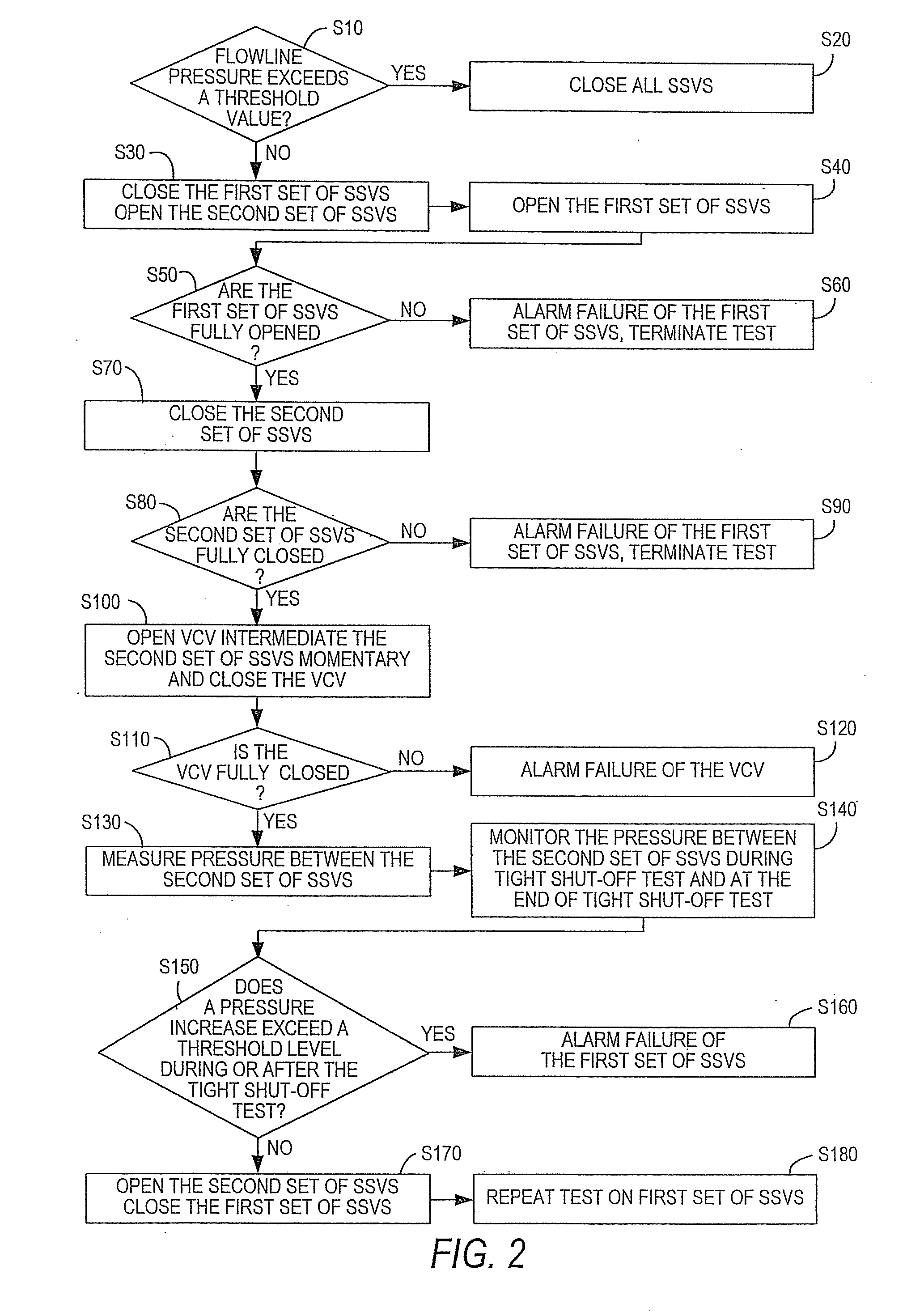
[0037]Two sets of surface safety valves (SSVs) 11, 12 and 13, 14 are in fluid communication with the inlet 1 and the outlet 2 are thereby operable as a flowline for the fluid product. Each set of SSVs, identified and referred to as SSV-1 and SSV-2, has two SSVs 11-12 and 13-14, respectively, which are connected in series. The SSVs close automatically in the a...


PUM


Abstract

A high integrity protection system (HIPS) for protection of a pipe downstream of a wellhead includes: an inlet connected to the wellhead; outlet connected to the downstream pipe; two sets of two series-connected surface safety valves (SSVs) in fluid communication with the inlet and outlet, the two sets being in parallel fluid flow relation to each other, either one or both of the sets of SSVs operable as a flowpath for fluids entering the inlet and passing through the outlet to the downstream pipe; two vent control valves (VCVs), each connected to piping intermediate one set of series-connected SSVs, the VCVs being in fluid communication with a vent line, whereby, upon opening of a VCV, process pressure between the two SSVs is vented; a signal-generating safety logic solver, in accordance with preprogrammed safety and operational protocols; and pressure sensing transmitters attached to piping upstream of the HIPS outlet.

Description

RELATED APPLICATION[0001]This application claims priority to and is a divisional of U.S. patent application Ser. No. 11 / 648,312 filed on Dec. 29, 2006, which is incorporated herein by reference.FIELD OF THE INVENTION[0002]The present invention relates to a method and an apparatus for the operation and testing of a high integrity protection system (HIPS) connected to a wellhead pipeline system.BACKGROUND OF THE INVENTION[0003]In the oil and gas industry, production fluid pipelines downstream of the wellhead are generally thin-walled in order to minimize the cost of the pipeline. It is therefore necessary that such pipelines be protected against excessive pressure that might rupture the pipe, which would be very expensive to replace and cause environmental pollution. A conventional system used to protect pipelines from over-pressure is the high integrity protection system (HIPS). This is typically an electro-hydraulic system employing pressure sensors to measure the pressure in the pi...

Claims


Application Information

Patent Timeline
Patent Type & Authority Applications(United States)
IPC IPC(8): F16K31/02G01M99/00
CPCF17D5/00E21B33/03Y10T137/87507Y10T137/7761Y10T137/7728Y10T137/87314Y10T137/87877Y10T137/87772Y10T137/87265
Inventor FLANDERS, PATRICK S.
Owner SAUDI ARABIAN OIL CO
Why Eureka
Try Eureka