Dental Implant Fixture

a technology for dental implants and fixtures, applied in dental surgery, fastening prostheses, medical science, etc., can solve the problems of high research and development, bone decay and bone damage, and achieve the effects of reducing defects, preventing bone decay and bone damage, and increasing total productivity

Inactive Publication Date: 2011-03-31
COTEC CORP
View PDF6 Cites 3 Cited by
  • Summary
  • Abstract
  • Description
  • Claims
  • Application Information

AI Technical Summary

Benefits of technology

[0024]The above-configured dental implant fixture according to present embodiments is provided with 3 or more ridged portions in cuter periphery with mutually different pitches.
[0025]Therefore, by uniformly distributing load across osseous tissue, bone decay and bone damage can be prevented.
[0026]Also, a dental implant fixture configured according to present embodiments has screw threads that decrease in pitch along one direction.
[0027]Because machining process of the screw threads is scientific, defects can be reduced, and total productivity can be increased.

Problems solved by technology

While other types of prosthetic or false teeth degenerate the surrounding teeth or bone over time, implants do not induce degeneration of surrounding teeth.
In addition, because implants can be used almost indefinitely, they are the subject of much research and development.
However, the following limitations are inherent in the above-configured fixture 10 according to the related art.
For the above reason, the fixture 10 is difficult to be implanted successfully, and the bone decay and bone damage can be resulted because load cannot be uniformly distributed.

Method used


Image

  • Dental Implant Fixture
  • Dental Implant Fixture
  • Dental Implant Fixture

Examples


Embodiment Construction

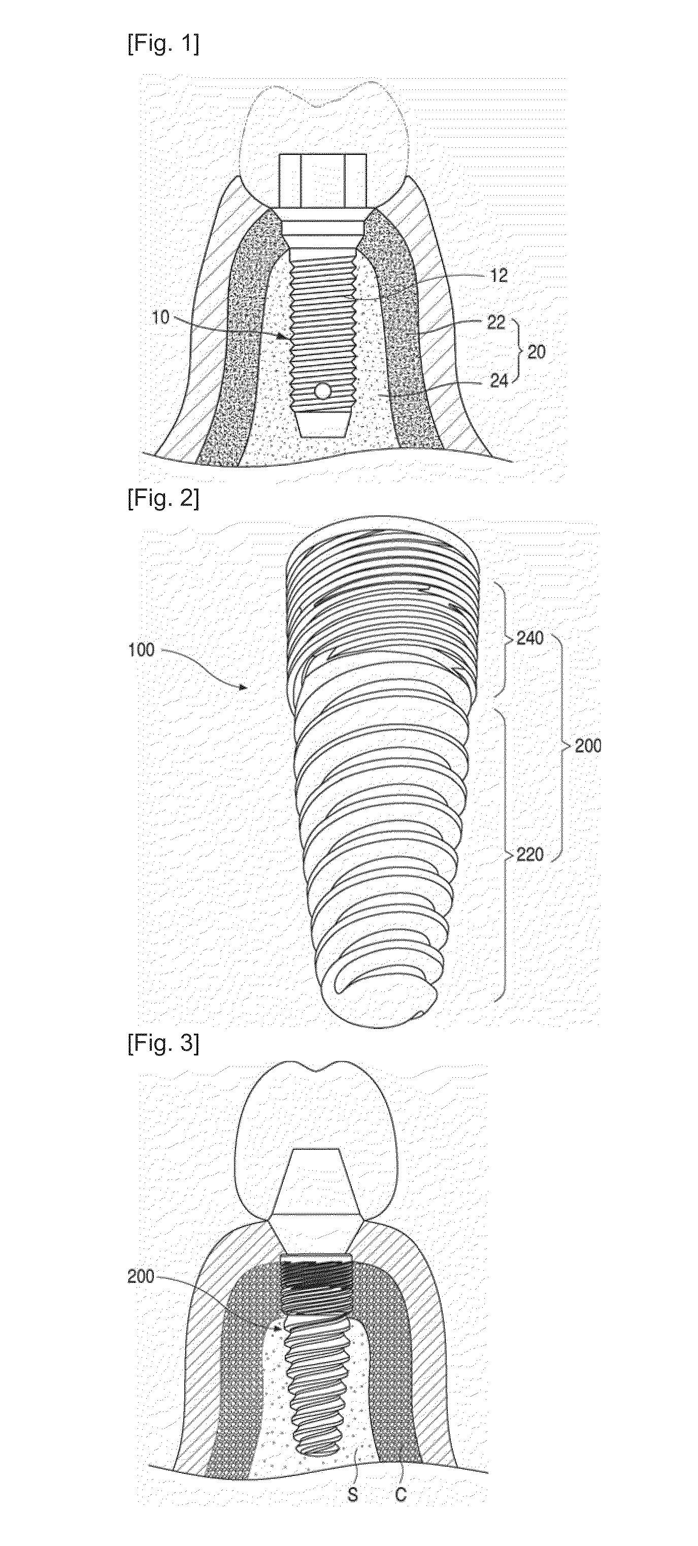
[0033]A description will be provided below of the structure of a dental implant fixture (hereinafter called a ‘fixture’) according to present embodiments, with reference to FIGS. 2 and 3.

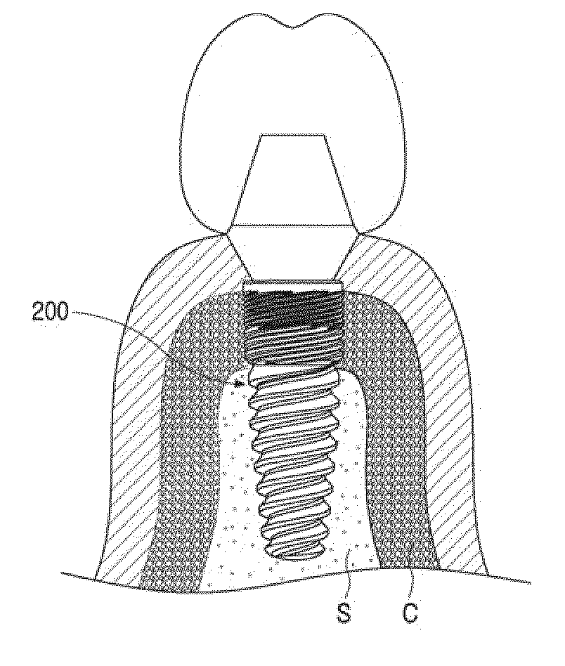
[0034]FIG. 2 is an upward perspective view of a dental implant fixture according to a present embodiment, and FIG. 3 is a view showing an implanted dental implant fixture according to a present embodiment.

[0035]Referring to FIGS. 2 and 3, a fixture 100 according to present embodiments is shaped as a column with screw threads defined in its alter periphery, and is implanted in a dental alveolus (not shown).

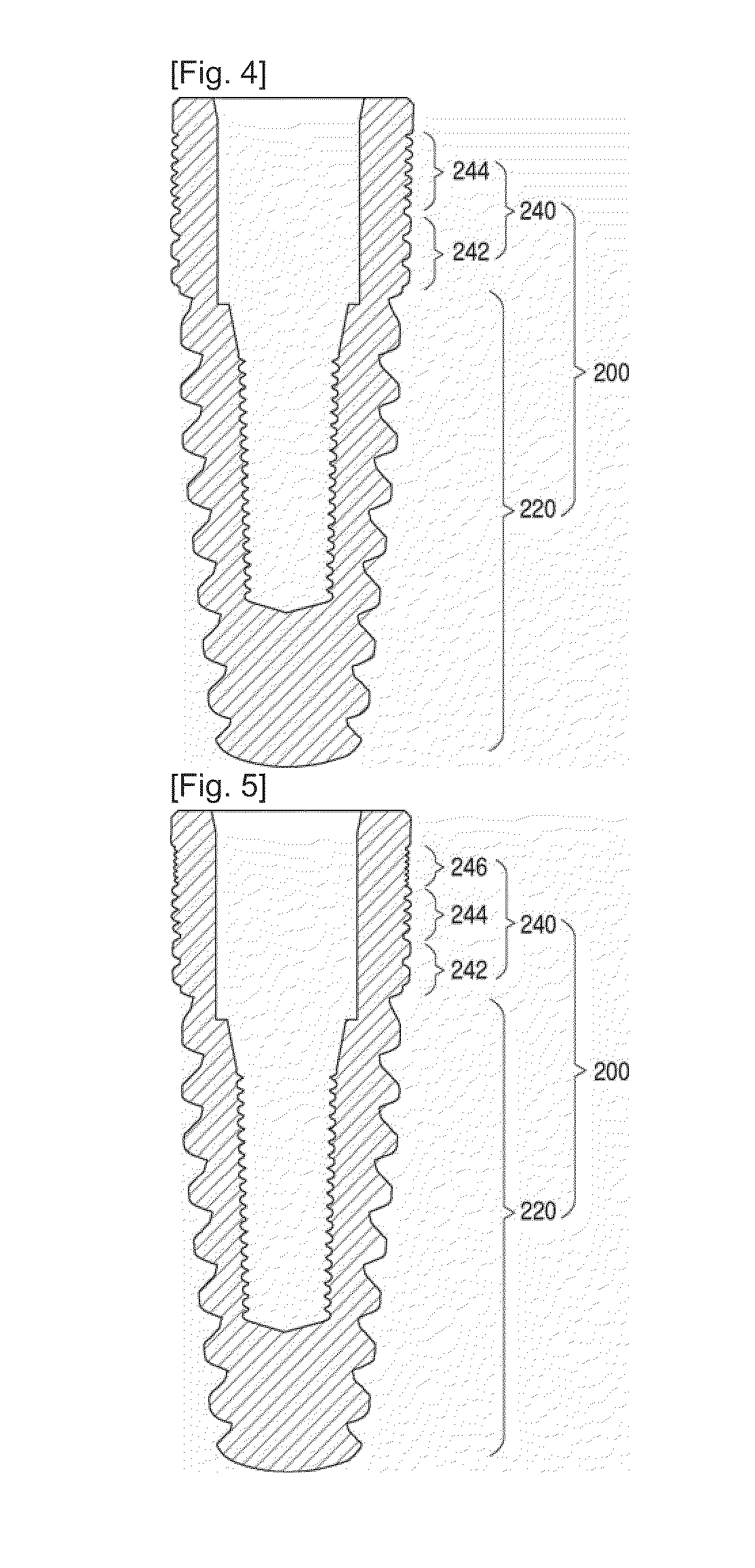
[0036]Specifically, the cuter periphery of the fixture 100 is provided with three or more parts of ridged portions 200 having mutually different pitches, and the ridged portions 200 progressively decrease in pitch upward.

[0037]Accordingly, the ridged portions 200 have an upper outer peripheral pitch that is less than the lower cuter peripheral pitch.

[0038]The ridged portions 200 are configured to i...


PUM


Abstract

Provided is a dental implant fixture with 3 or more ridged portions having mutually different pitches to distribute load uniformly across osseous tissue. The pitches of the ridged portions (200) progressively decrease in one direction. The ridged portions (200) include a larger ridged portion (220) that contacts spongy bone with low bone density, and a smaller ridged portion (240) that contacts cortical bone with high bone density. The smaller ridged portion (240) is provided with 2 or more threaded regions with respectively different pitches. With this configuration, bone decay and bone damage can be prevented, and synostosis can be improved.

Description

TECHNICAL FIELD[0001]The present disclosure relates to a dental implant fixture provided with 3 or more ridged portions having mutually different pitches to distribute load uniformly across osseous tissue.BACKGROUND ART[0002]While implants in general denote replacement material for restoring lost human anatomical components, in dentistry, implants are prosthetic tooth roots that allow prosthetic teeth to be implanted.[0003]Specifically, a dental implant fixture is usually made of titanium that the human body does not reject in order to replace roots of teeth that are lost, and are implanted and fixed in bone from which teeth have fallen cut. Prosthetic teeth are fixed to such implants to restore the functions of lost teeth.[0004]While other types of prosthetic or false teeth degenerate the surrounding teeth or bone over time, implants do not induce degeneration of surrounding teeth. Also, implants are virtually the same in terms of function and form as the original natural teeth the...

Claims


Application Information

Patent Timeline
Patent Type & Authority Applications(United States)
IPC IPC(8): A61C13/225
CPCA61C8/0025A61C8/0022A61C8/00
Inventor CHOI, JU WON
Owner COTEC CORP
Why Eureka
Try Eureka