Sound signal processing apparatus, sound signal processing method, display apparatus, rack, program, and storage medium

a sound signal processing and display device technology, applied in the field of sound signal processing apparatus, sound signal processing method, display device, rack, program, storage medium, can solve the problem of sound image not positionally, and achieve the effect of eliminating sound quality deterioration, reducing correlation between the first and second signals, and enhancing respective bandwidths

Inactive Publication Date: 2011-05-19
SHARP KK
View PDF8 Cites 9 Cited by
  • Summary
  • Abstract
  • Description
  • Claims
  • Application Information

AI Technical Summary

Benefits of technology

[0027]In order to attain the object, a sound signal processing apparatus of the present invention is a sound signal processing apparatus for processing a stereo sound signal containing a first sound signal and a second sound signal, the sound signal processing apparatus including: a first equalizer for enhancing a bandwidth covering a frequency of 8 kHz of the first sound signal; a second equalizer for enhancing a bandwidth covering the frequency of 8 kHz of the second sound signal; and a filter for delaying a phase of the first sound signal outputted from the first equalizer, or a phase of the first sound signal to be inputted in the first equalizer.
[0028]The arrangement enhances respective bandwidths covering 8 kHz of the first sound signal and the second sound signal. Therefore, in a case where the first sound signal and the second sound signal contain a common monaural sound, a listener is more likely to perceive that a sound image of the monaural sound is located above a midpoint between paired speakers which are driven according to the first sound signal and the second sound signal. In addition, the phase of the first sound signal is delayed according to the arrangement. This decreases correlation between the monaural sound contained in the first sound signal and that of the second sound signal. As a result, the sound image of the monaural sound is diffused more than a sound image obtained by merely enhancing the bandwidths covering 8 kHz. Furthermore, the use of the first equalizer and the second equalizer results in that the correlation between the first and second signals is decreased in a greater proportions of the first and second signals, as compared to a case where the phase of the first sound signal is merely delayed (i.e., a case where the first equalizer and the second equalizer are not provided). A synergistic effect brought about by these causes further diffusion of the sound image. This makes it possible to obtain a sufficient distance of upward movement of the sound image.
[0029]Furthermore, according to the arrangement, the first sound signal and the second sound signal are processed independently. Accordingly, a sound contained in the first sound signal is not mixed in the second sound signal, and vice versa. This eliminates sound quality deterioration such as a change in tone, and that disruption of sound image localization which is due to right-and-left movement of a listener. This also prevents a sound image from being localized outside a range between two right and left speakers provided under a display panel, in a case where the arrangement is applied to a TV of the under-speaker type, a TV rack housing speakers, etc.
[0032]According to the arrangement, the first sound signal and the second sound signal which are to be outputted from the sound signal processing apparatus have a same level, provided that the first sound signal and the second sound signal both inputted in the sound signal processing apparatus have a same level. This makes it possible to sufficiently move a sound image upward in an elevation direction, without causing both a change in tone and movement of the sound image in an azimuth direction due to an interaural sound pressure level difference.
[0034]According to the arrangement, in the 8 kHz band, it is possible to obtain a sufficient phase delay amount for diffusing a sound image. In addition, it is possible to suppress a phase delay amount small in a bandwidth in which an interaural time difference affects perception of a sound image (i.e., in a bandwidth not higher than 1.6 kHz). This makes it possible to sufficiently move a sound image upward in an elevation direction, without causing movement of the sound image in an azimuth direction due to an interaural time difference.
[0036]The arrangement makes it possible to obtain a sufficient distance of upward movement of a sound image, as is the case with the sound signal processing apparatus. In addition, this eliminates (i) sound quality deterioration such as a change in tone due to addition or subtraction between the first sound signal and the second sound signal, and (ii) that disruption of sound image localization which is due to right-and-left movement of a listener. Furthermore, this prevents a sound image from localizing outside a range between two right and left speakers provided under a display panel in a case where the sound signal processing apparatus is applied to a TV of the under-speaker type or a TV rack housing speakers.

Problems solved by technology

This leads to the following problems.
This leads to a problem in that the sound image does not positionally match a video image displayed on the display panel.

Method used


Image

  • Sound signal processing apparatus, sound signal processing method, display apparatus, rack, program, and storage medium
  • Sound signal processing apparatus, sound signal processing method, display apparatus, rack, program, and storage medium
  • Sound signal processing apparatus, sound signal processing method, display apparatus, rack, program, and storage medium

Examples


embodiment 1

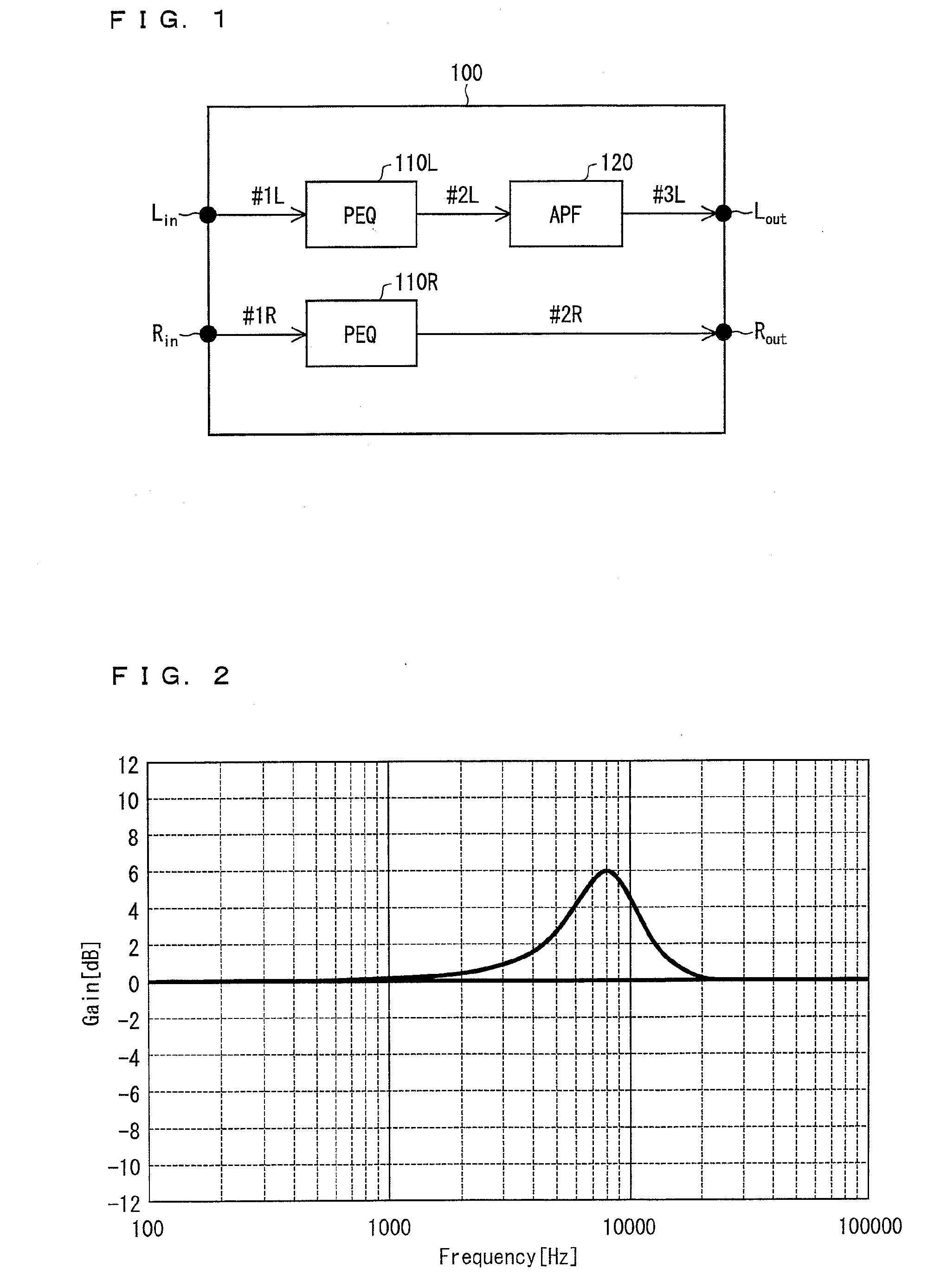
[0055]The following describes one embodiment of a sound signal processing apparatus of the present invention, with reference to figures. Since the sound signal processing apparatus of the present embodiment is realized as a circuit housed in AV equipment, hereinafter, the sound signal processing apparatus is referred to as “sound signal processing circuit,” and labeled with a reference sign “100.”

[0056]The following describes an arrangement of the sound signal processing circuit 100, with reference to FIG. 1.

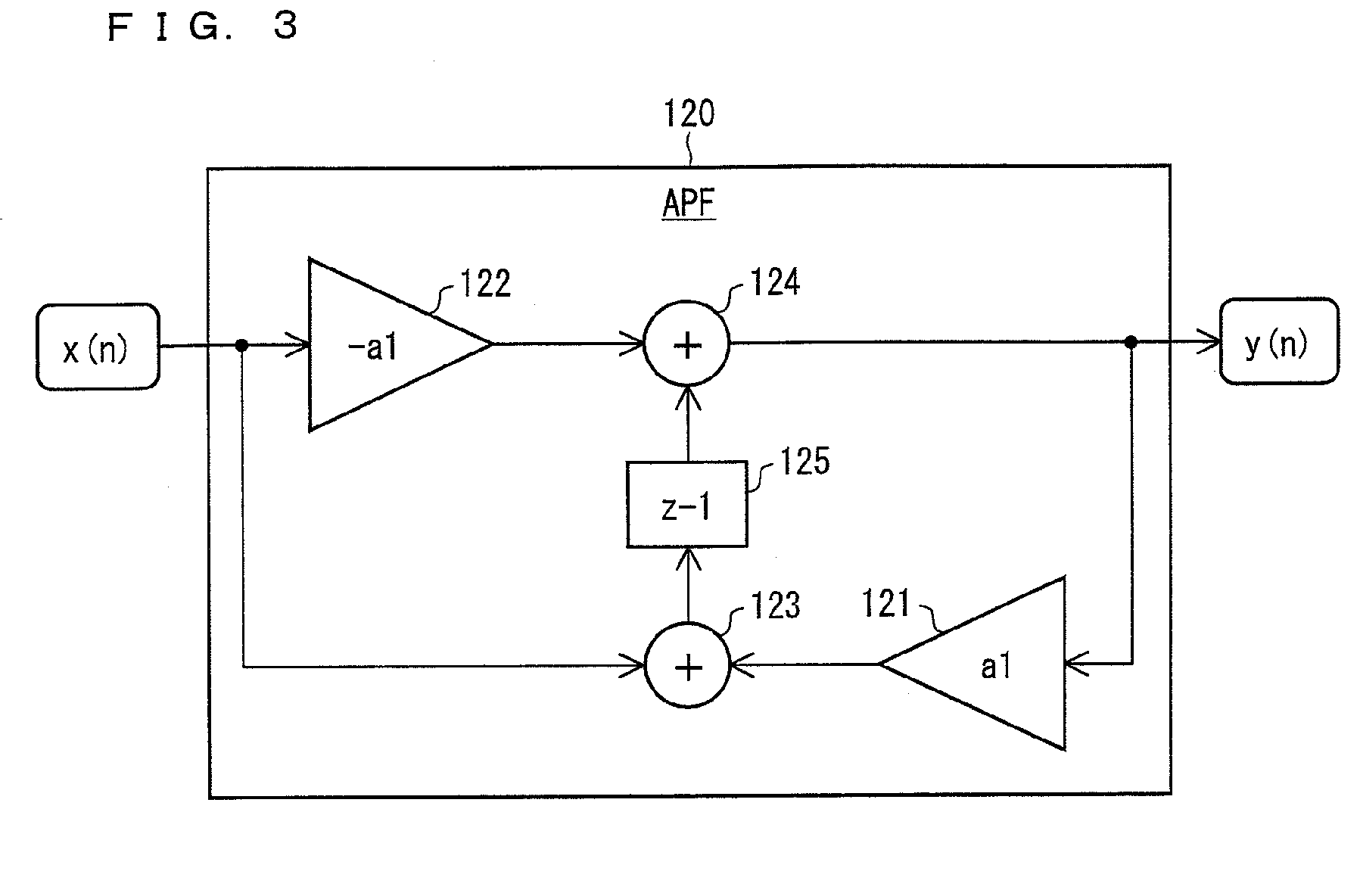
[0057]FIG. 1 is a block diagram illustrating the arrangement of the sound signal processing circuit 100. On the whole, the sound signal processing circuit 100 is a sound signal processing circuit which processes a stereo sound signal received via an input section Lin and a stereo sound signal received via an input section Rin, and outputs the processed stereo sound signals via an output section Lout and an output section Rout. In AV equipment provided with the sound signal proce...

embodiment 2

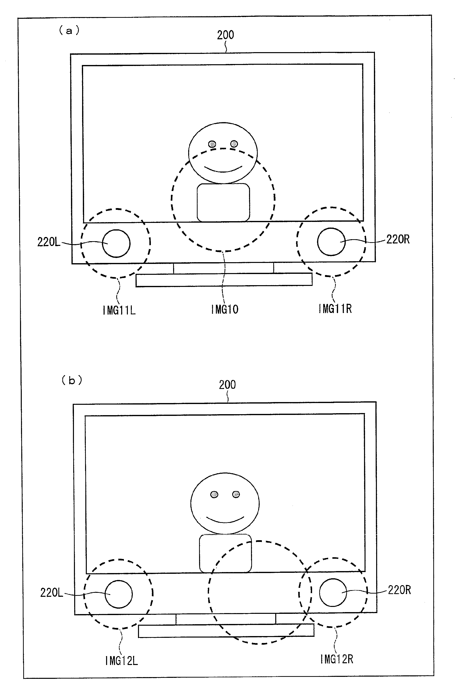
[0087]The following describes one embodiment of a display apparatus of the present invention, with reference to figures. Since the display apparatus of the present embodiment is realized as a television receiver, hereinafter, the display apparatus is referred to as “TV” and labeled a reference sign “200.”

[0088]FIG. 7 is an elevation view of a TV 200. As illustrated in FIG. 7, the TV 200 includes a display panel 210 and speakers 220L and 220R. In addition, the TV 200 houses the sound signal processing circuit 100 illustrated in FIG. 1 although this is not illustrated.

[0089]As illustrated in FIG. 7, the TV 200 is a TV of the under-speaker type. That is, the speakers 220L and 220R are provided under the display panel 210 (on a floor side in a proper installed state). The TV 200 outputs, from the speakers 220L and 220R, stereo sound associated with a video image to be displayed on the display panel 210.

[0090]The TV 200 is arranged such that stereo sound signals received via a tuner (or ...


PUM


Abstract

A sound signal processing apparatus (100) includes: an equalizer (110L) for enhancing an 8 kHz band of a sound signal (#1L); an equalizer (110R) for enhancing an 8 kHz band of a sound signal (#1R); and a filter (120) for delaying a phase of a sound signal (#2L). The filter (120) decreases correlation between the sound signals (#3L) and (#2R). This sufficiently moves a sound image upward, without use of a technique of pseudo surround.

Description

TECHNICAL FIELD[0001]The present invention relates to a sound signal processing apparatus for processing a stereo sound signal and to a sound signal processing method for processing a stereo sound signal. In addition, the present invention relates to a display apparatus having the sound signal processing apparatus and to a rack having the sound signal processing apparatus. Furthermore, the present invention relates to a program for causing a digital signal processor to operate as the sound signal processing apparatus and to a storage medium storing the program.BACKGROUND ART[0002]Television receivers (hereinafter, referred to as “TV”) are usually configured to be stereo-capable, thereby being compatible with stereo broadcast. Such televisions have a pair of speakers for outputting stereo sound associated with a video image to be displayed. Such speakers are classified into a side-speaker type and an under-speaker type, depending on their layouts. The side-speaker type refers to a la...

Claims


Application Information

Patent Timeline
Patent Type & Authority Applications(United States)
IPC IPC(8): H04N5/60H04R5/00
CPCH04N5/607H04R5/04H04R2430/03H04N21/439H04S1/002H04S2420/01H04R2499/15
Inventor KUBO, KATSUTOSHI
Owner SHARP KK
Why Eureka
Try Eureka