Electrical pressfit plug connector having a laterally bent power pin

a technology of power pins and plug connectors, which is applied in the manufacture of contact members, coupling device connections, fixed connections, etc., can solve the problems of increased costs per individual use and unusable area of printed circuit boards, and achieve cost-effective effects

Active Publication Date: 2011-06-02
ROBERT BOSCH GMBH
View PDF8 Cites 3 Cited by
  • Summary
  • Abstract
  • Description
  • Claims
  • Application Information

AI Technical Summary

Benefits of technology

[0005]According to the exemplary embodiments and/or exemplary methods of the present invention, it is provided that one should position the contact pins and pressfit pins of one or more outer contacts of the pressfit plug connector in a manner offset laterally to one another, in order that one may use the same printed circuit board contour (narrow printed circuit board having no cut-away portion), optimized as to utilization, for both narrow and wide customer plugs. In othe

Problems solved by technology

This has the result that not only the position of the contact pins within the pressfit plug connector is predefined because of the customer plug, but also the positions of the metallized bores in the printed circuit board.
This widening of the printed circuit boa

Method used


Image

  • Electrical pressfit plug connector having a laterally bent power pin
  • Electrical pressfit plug connector having a laterally bent power pin

Examples


Embodiment Construction

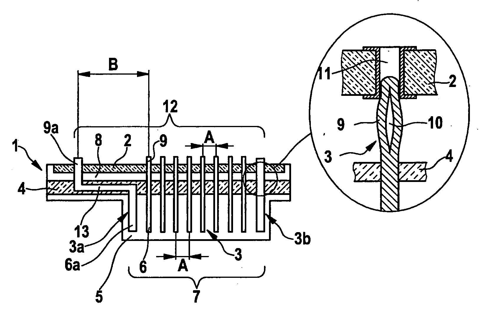
[0011]Electrical pressfit plug connector 1, shown in FIG. 1, is fastened on a printed circuit board 2, using a pressfit technique.

[0012]Pressfit plug connector 1 includes electrical contacts 3, which are fastened in the bores of a contact carrier plate 4 that is made of electrically insulating material, and project on both sides of contact carrier plate 4. On the one side of contact carrier plate 4, namely, on the front side 5 facing away from the printed circuit board of plug connector 1, contacts 3 are configured as parallel contact pins 6 for contacting a customer plug or counterplug, and situated as a male multipoint connector 7 (contact spacing A). On the other side of contact carrier plate 4, namely, on back side 8, facing the printed circuit board, of pressfit plug connector 1, contacts 3 are configured as parallel, deformable pressfit pins 9, having a springy core 10 for pressfitting in metallized bores 11 in printed circuit board 2, and are also situated as a male multipoin...


PUM


Abstract

An electrical pressfit plug connector for fastening to a printed circuit board includes contacts, which on the front side and back side of the plug connector are each situated as a single or multi-row male multipoint connector, and which are configured on the front side of the plug connector as contact pins for contacting a counterplug, and are configured on the back side as pressfit pins for pressfitting into metallized bores in the printed circuit board, according to the present system, either the contact pin or the pressfit pin of at least one contact of the male multipoint connectors being situated laterally offset with respect to its associated pressfit pin and contact pin, respectively, in the longitudinal direction of the male multipoint connectors.

Description

FIELD OF THE INVENTION[0001]The present invention is based on an electrical pressfit plug connector.BACKGROUND INFORMATION[0002]An electrical pressfit plug connector is discussed in EP 0 901 188 A2, for example.[0003]In today's control units in printed circuit board technology, the electrical connection from the customer plug to the printed circuit board is produced using pressfit plug connectors, whose contacts are configured at one end as contact pins of a front side male multipoint connector for contacting the customer plug and at the other end as deformable pressfit pins of a back side male multipoint connector for pressfitting in sleeves or metallized bores in the printed circuit board. A gas-tight and electrically conductive connection is created by the pressfitting, between the pressfit pins and the printed circuit board bores. In the known pressfit plug connectors, the pressfit pins and the contact pins of the individual contacts are each symmetrical to the center line or ce...

Claims


Application Information

Patent Timeline
IPC IPC(8): H01R13/02H01R12/50H01R12/58
CPCH01R12/585H01R43/16H01R23/68
Inventor EMDE, CHRISTOPHSCHOEN-HERMENAU, RUEDIGERBUHMANN, MITJA
Owner ROBERT BOSCH GMBH
Why Eureka
Try Eureka