Conversion set for a tube bundle heat exchanger

a heat exchanger and conversion set technology, which is applied in the direction of heat exchanger fastening, mounting, lighting and heating apparatus, etc., can solve the problems of increasing energy costs of plants, reducing the efficiency of tube bundle heat exchangers, so as to achieve easy repair or maintenance of the plate heat exchanger unit, the effect of simple connection

Active Publication Date: 2011-06-16
GESMEX
View PDF6 Cites 13 Cited by
  • Summary
  • Abstract
  • Description
  • Claims
  • Application Information

AI Technical Summary

Benefits of technology

[0020]In a further variant provision can be made that on the through hole of each mounting plate a first flange is arranged and a further flange is provided on each mounting plate. Due to the flanges a very simple connection of the plate heat exchanger unit to the existing connections of the tube bundle heat exchanger is possible for the feeding and discharge of heat transfer media. In addition a plurality of plate heat exchanger units can be connected together in this way. The flange joints are easily released so that repairs or maintenance on the plate heat exchanger unit are easily possible or the plate heat exchanger unit can be easily replaced.
[0021]However provision can be made that on the through hole of each mounting plate a first pipe weld end is arranged and a further pipe weld end is provided on each mounting plate. The pipe weld ends can be joined to existing connections of the tube bundle heat exchanger for feeding and discharging heat transfer media in that a welded joint is applied. In this way a reliable connection is possible and no seals, such as for example with a flange joint, are needed.
[0022]Expediently, provision can be made that a support plate is arranged on the inner side of each mounting plate and each mounting plate is connected by means of the support plate to the respective outer heat exchanger plate of the plate packet. In this way the manufacture of the plate packet is simplified and an improved connection between the relatively thick mounting plate and the very thin heat exchanger plate can be facilitated.
[0023]In another furt...

Problems solved by technology

A disadvantage with tube bundle heat exchangers is that due to the laminar flow in the tubes and the relatively thick tube walls, which may be 2 to 3 mm thick, only low heat transmission coefficients and thus a low efficiency of the tube bundle heat exchangers can be achieved.
Consequently, large heat...

Method used


Image

  • Conversion set for a tube bundle heat exchanger
  • Conversion set for a tube bundle heat exchanger
  • Conversion set for a tube bundle heat exchanger

Examples


Embodiment Construction

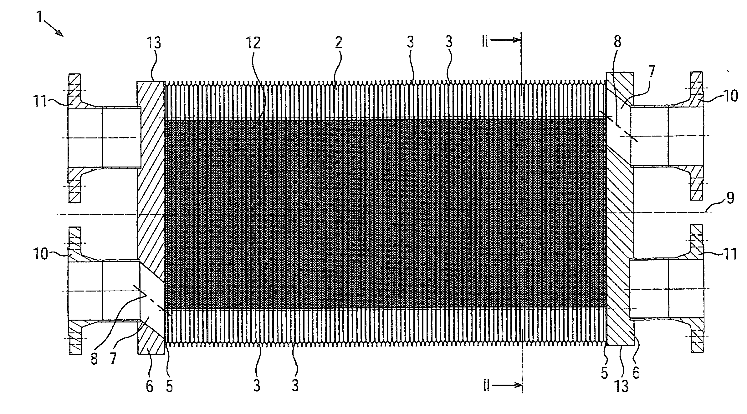
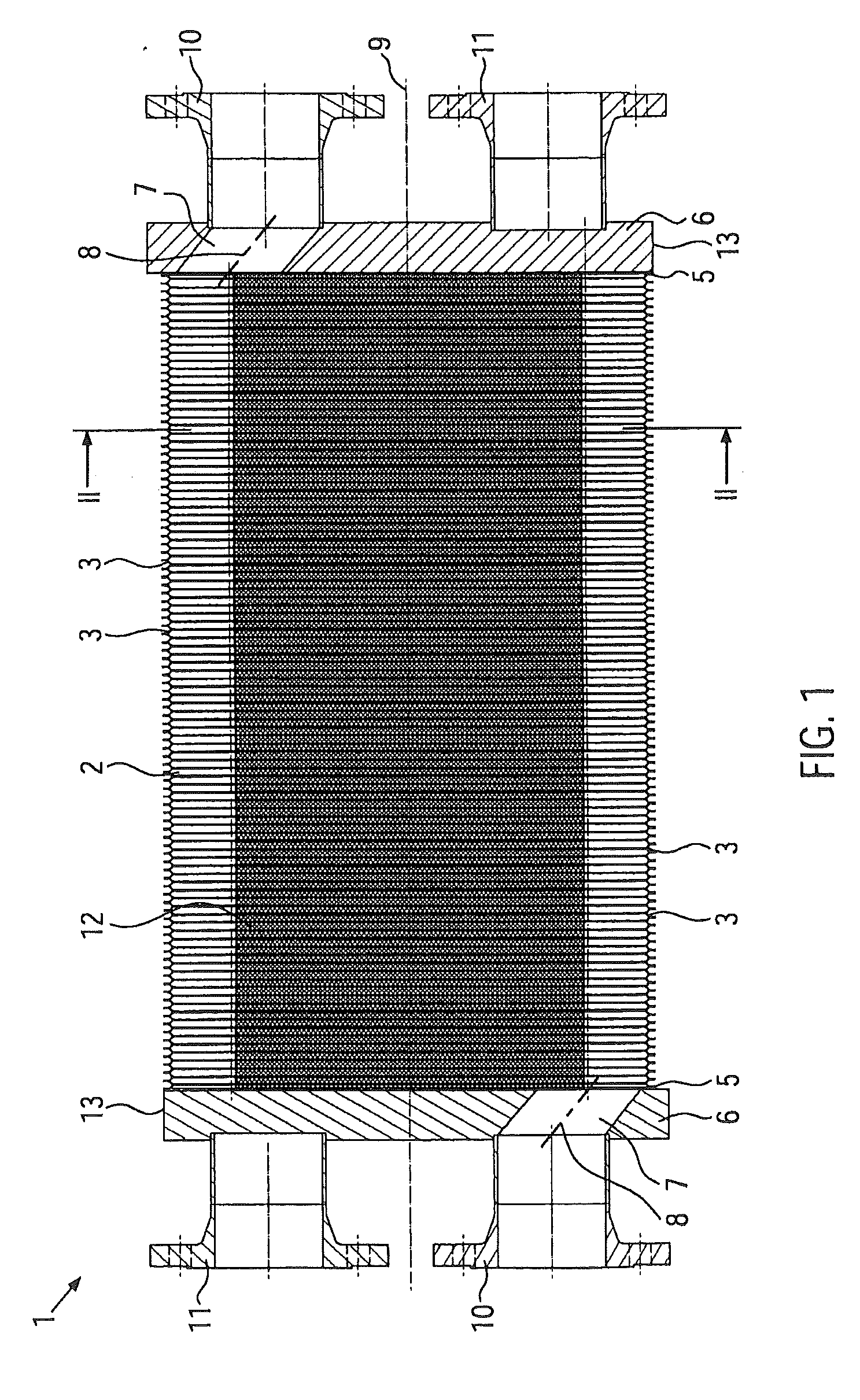
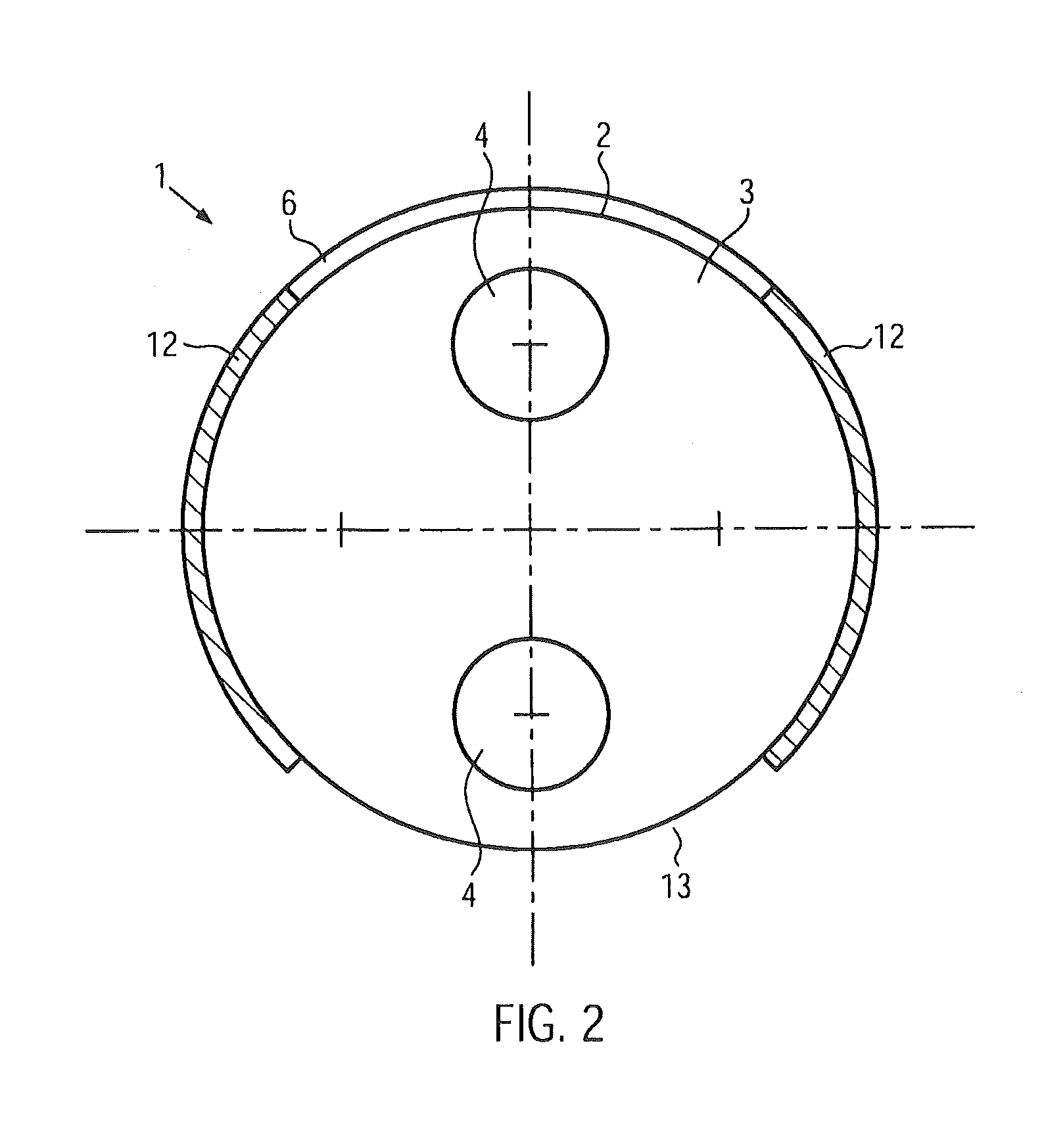
[0032]FIG. 1 illustrates a side view of a plate heat exchanger unit 1. The plate heat exchanger unit 1 comprises a plate packet 2 which comprises at least two heat exchanger plates 3. In the present case the plate packet 2 comprises a large number of heat exchanger plates 3. Each heat exchanger plate 3 has at least one through hole 4, preferably two through holes 4. This can be seen for example in FIG. 2. In each case two heat exchanger plates 3 are joined together along their through holes 4, preferably by welding. The plate pairs thus created are welded together along the periphery of the heat exchanger plates 3 so that the plate packet 2 is produced. The thickness of the heat exchanger plates 3 is about 0.6 to approximately 1 mm. It is also conceivable however to use thicker or thinner heat exchanger plates.

[0033]At both ends of the plate packet 2 in each case the outer heat exchanger plate 3 is joined to a support plate 5, preferably by welding. The heat exchanger plates 3 are p...


PUM


Abstract

The present invention relates to a conversion set for a pipe bundle heat exchanger having a cylindrical housing. Using said conversion set, existing tube bundle heat exchangers can be changed over such that the efficiency and thus the heat transfer thereof is improved, large exchange surface areas are provided, and energy costs are reduced. The conversion set can also be used in high-pressure applications for pressures above 300 bar. According to the invention, the conversion set has at least one plate heat exchanger unit for replacing the tube bundle unit, comprising at least the following components: a plate packet having at least two heat exchanger plates, each comprising at least one through hole and welded to each other in pairs along the periphery thereof or along the periphery of the through holes, two mounting plates each having at least one through hole, wherein one each of the mounting plates is arranged at each end of the plate packet and is connected to each outermost heat exchanger plate of the plate packet, and at least one tension means extending in the longitudinal axis between the mounting plates and connected to both mounting plates, so that the two mounting plates and the tension means form a cage about the plate packet, said cage absorbing the forces arising in the plate packet in the operating state of the plate heat exchanger unit, wherein the outer diameter of the plate heat exchanger unit is adapted to the inner diameter of the cylindrical housing of the tube bundle heat exchanger, and the tension means is designed as a flow director extending at least partially around the periphery of the plate packet.

Description

CROSS-REFERENCE TO RELATED APPLICATION[0001]This application is a U.S. national stage application of International Application No. PCT / EP2008 / 004905, which has an international filing date of Jun. 18, 2008.BACKGROUND OF THE INVENTION[0002]1. Field of the Invention[0003]The invention relates to a conversion set for a tube bundle heat exchanger having a cylindrical housing.[0004]2. Description of Related Art[0005]Tube bundle heat exchangers are often used in process plants in industry. A tube bundle heat exchanger normally consists of an outer jacket or an outer housing and a tube bundle located in the interior, i.e., arranged in the housing. The exchange of the process heat takes place between these two separate compartments. The heat from a first hot heat transfer medium is absorbed by a second heat transfer medium which is to be heated up, by means of which the energy transfer is realised. Tube bundle heat exchangers are very strong and can therefore be used for applications with h...

Claims


Application Information

Patent Timeline
IPC IPC(8): F28F9/00
CPCF28D9/0012F28D9/0031F28F2280/02F28F9/005F28F2275/06F28F9/001
Inventor HALLMANN, MIKEHORNIG, JORGENGELS, DIETER
Owner GESMEX
Why Eureka
Try Eureka