System and device for measuring voltage in a conductor

a technology of conductor and voltage measurement, which is applied in the direction of moving iron instruments, instruments, base elements, etc., can solve the problems of a serious problem for the lack of voltage sensors, and impeded development of such a line-mounted power line monitor

Active Publication Date: 2011-06-23
GRID2020
View PDF52 Cites 28 Cited by
  • Summary
  • Abstract
  • Description
  • Claims
  • Application Information

AI Technical Summary

Problems solved by technology

However, development of such a line-mounted power line monitor has been impeded by the lack of a suitable voltage sensor.
This requirement presents a serious problem for the line-mounted power line monitor for two reasons.
Should there be a short circuit in a device that is connected between earth-ground and the feeder conductor; a powerful explosion could easily result, making the installation of any such device very hazardous to utility workers.
Secondly, the geometry of the pole configuration may prevent safe access to earth-ground for such a device.
It is apparent, however, that this device was developed for transmission lines rather than distribution feeders and does not have the ability to minimize interference from adjacent energized conductors.
In distribution feeder lines where the voltage can be as low as 2.4 kV, the spacing might be only two feet, making the interference from adjacent conductors a more serious source of error.
It would not be valid to calibrate out this error because in distribution feeder lines if one phase is lost, the other two phases would not necessarily be shut down.
This is significant ...

Method used


Image

  • System and device for measuring voltage in a conductor
  • System and device for measuring voltage in a conductor
  • System and device for measuring voltage in a conductor

Examples


Embodiment Construction

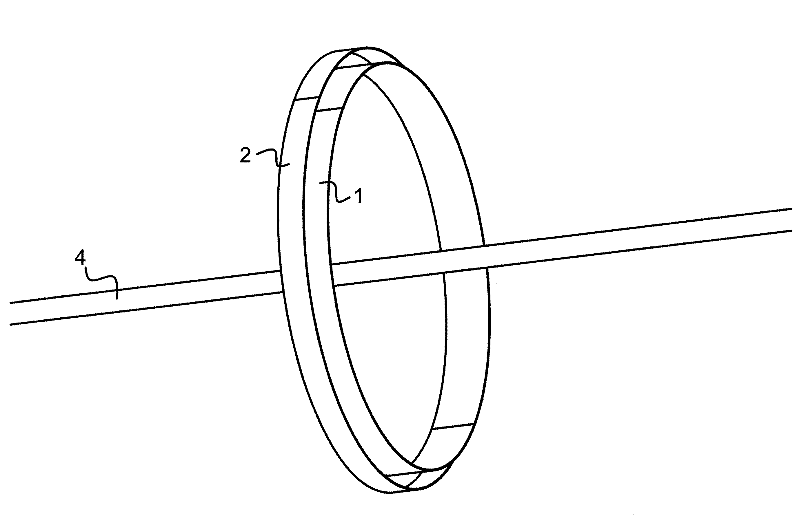
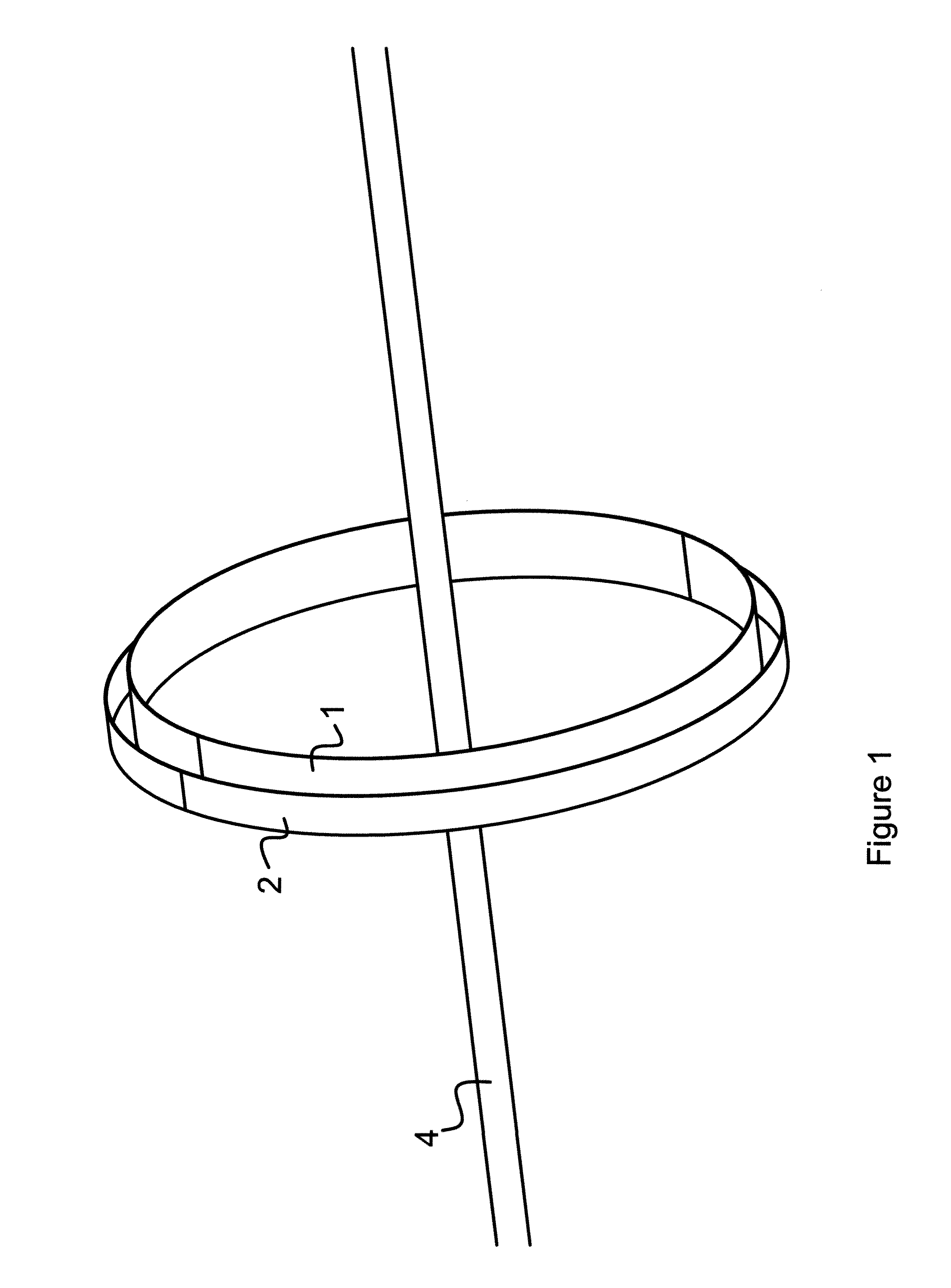
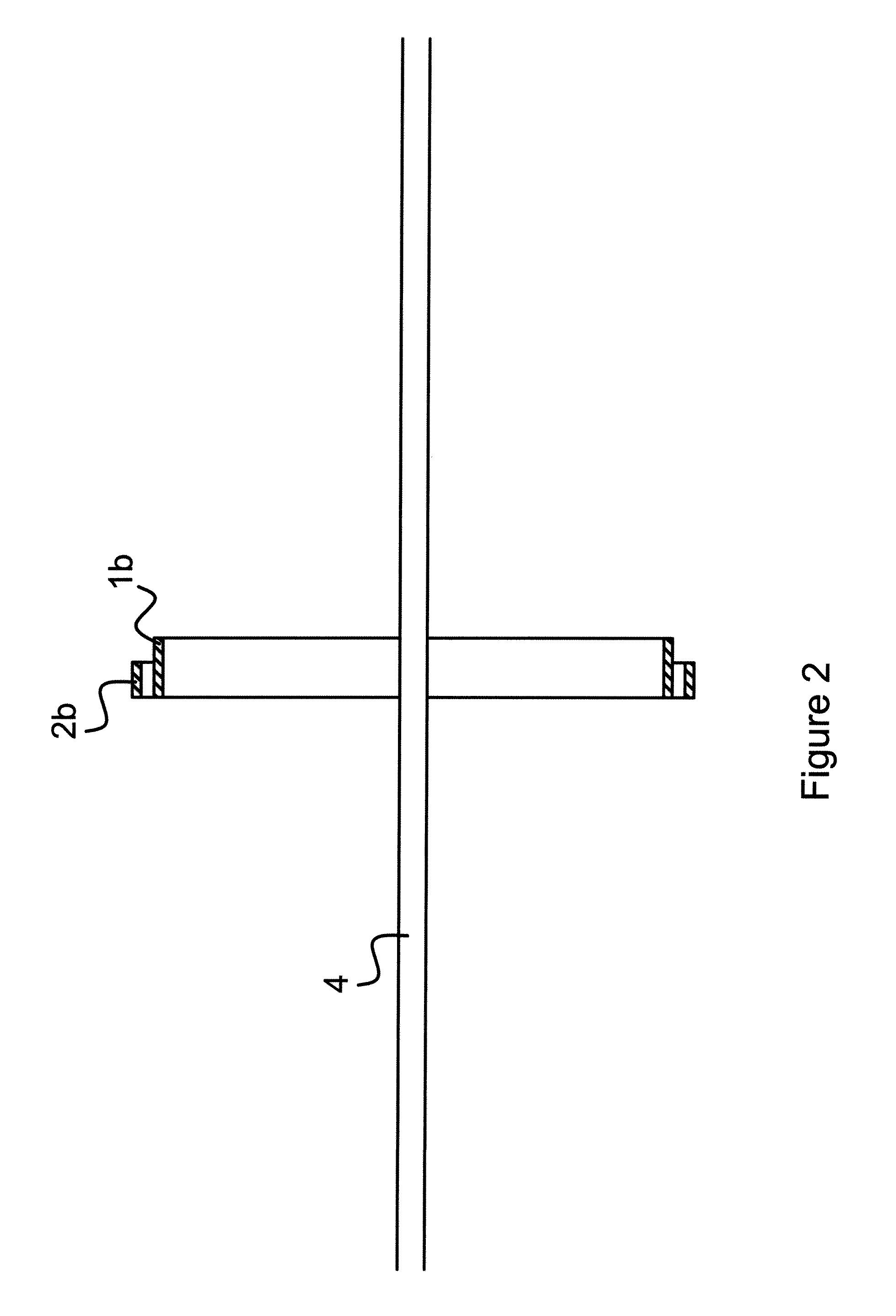
[0016]The system and device of the present invention derive a measure of voltage from the electrostatic field surrounding a conductor. A conductor having the same voltage as earth-ground will not have a measureable electrostatic field surrounding it. If the conductor has a voltage different than earth-ground, it will have an electric charge which produces a non-uniform field surrounding it. This field will have greater intensity closer to the conductor and lower intensity farther away. An electrode closer to the conductor will pick up more charge than an equivalent electrode farther away, and the difference in charge pickup will be greater for higher voltages on the conductor with respect to earth-ground than for lower voltages with respect to earth-ground. Thus, by measuring the difference in charge pickup between two different electrodes at different distances from the conductor, one can derive a measure of the voltage with respect to earth-ground without requiring any actual conn...


PUM


Abstract

A system and device for measuring voltage in a conductor having a voltage provides a first electrode surrounding and spaced from the conductor, and a second electrode surrounding and spaced from both the conductor and the first electrode such that there is no contact between the conductor and the electrodes or between the first and second electrodes. The first electrode is connected to a first input of a differential amplifier circuit and the second electrode is connected to the other input of the differential amplifier circuit. The output of the differential amplifier circuit provides a voltage signal in proportion to the voltage of the conductor, thus providing a non-contact means for measuring the voltage of a conductor without requiring a connection to ground while simultaneously providing a high level of rejection of external interference.

Description

FIELD OF THE INVENTION[0001]This invention relates generally to electric energy distribution systems. More specifically, the invention relates to a system and device for measuring the voltage of a conductor in situations where a connection to ground, or other known voltage, may be unsafe, impractical, or undesirable for other reasons. In one embodiment, the system of the invention may be used in a line-mounted device for measuring the voltage, and thus determining electrical parameters such as energy, the power factor, or the accumulated in-phase current in a distribution feeder.BACKGROUND OF THE INVENTION[0002]In U.S. Pat. No. 6,549,120 issued Apr. 15, 2003 to de Buda, “Device for sending and receiving data through power distribution transformers,” which is incorporated herein by reference, the idea of a line-mounted power line monitor which collects data on power flow in an electrical distribution feeder is presented. In order for such a power line monitor to be able to measure en...

Claims


Application Information

Patent Timeline
IPC IPC(8): G01R19/00
CPCG01R15/06G01R19/0046G01R19/0023
Inventor DE BUDA, ERIC GEORGE
Owner GRID2020
Why Eureka
Try Eureka